
This is a summary of a three part blogpost series at www.norwegiancreations.com
Introduction
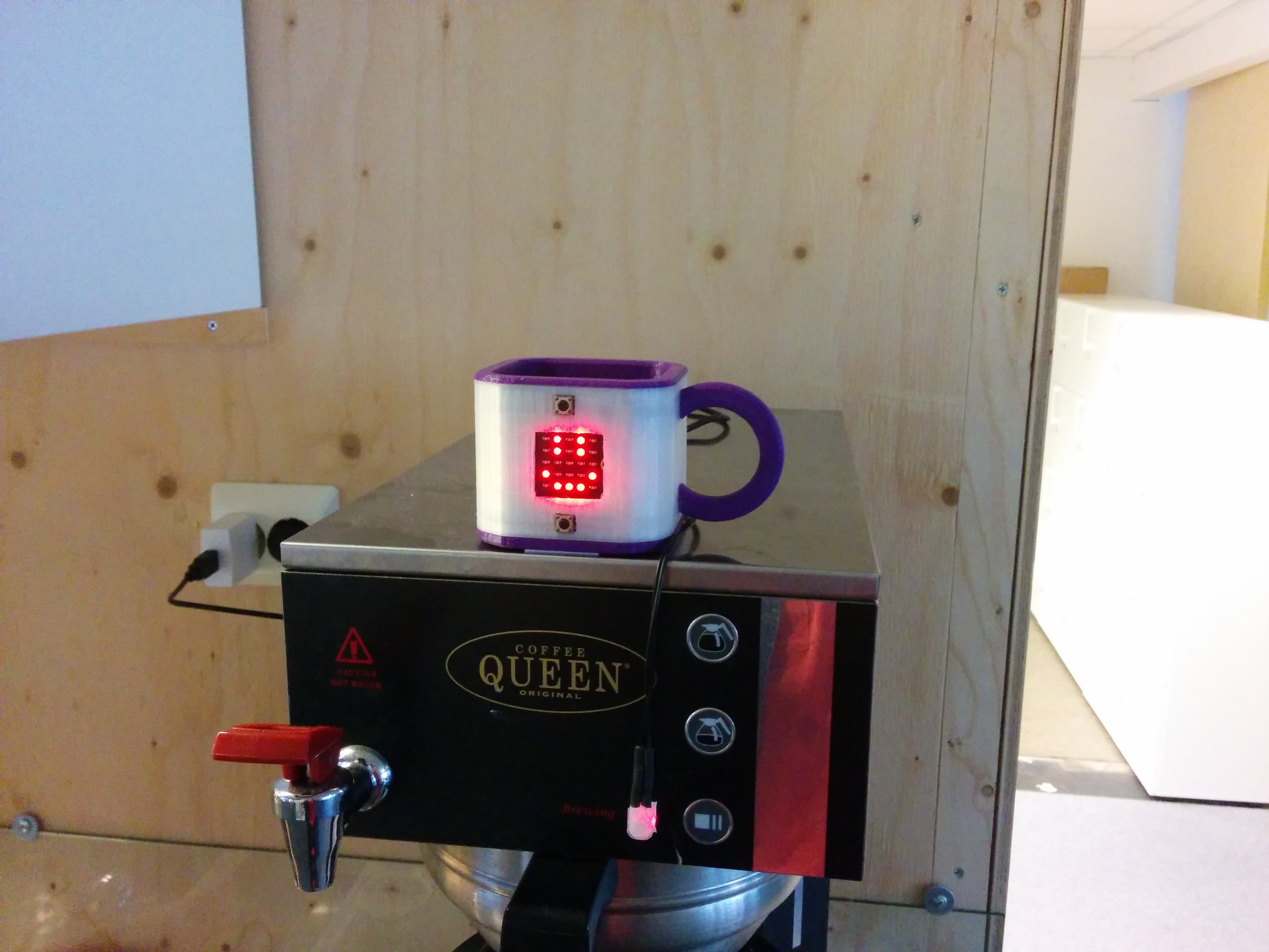
We at Norwegian Creations work out of the coworking space DIGS in Trondheim. In our office, we have a coffee maker capable of making large amounts of coffee. This is mostly a great thing, but not when the office is mostly empty due to summer vacation. Getting a cup of coffee turned into a game of chance, where you could end up with a sip of four hour old coffee. Things had to change.
We decided to augment our coffee maker with an indicator showing how old the coffee was. The machine has a LED which is turned on when new coffee is made, and off otherwise. This could be uses to detect when new coffee was brewed. In addition to showing how old the coffee is, we wanted to be notified on our desks when fresh coffee was ready.
Electronics
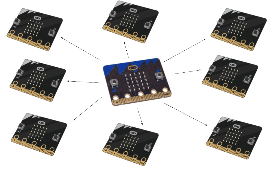
We based the system on the recently released BBC micro:bit, which is a small microcontroller board created as an educational tool in the UK. We had one laying around, and wanted to get to know it through a project. In addition, we received eight addition devices from Nordic to use as desktop receiver devices. The micro:bit comes with a built-in LED display, two buttons and loads of GPIO pins. The only external components we needed was an LDR (Light dependant resistor) in addition to a normal resistor. The components were connected in a voltage divider circuit, connected to the PIN 0 on the micro:bit. As the name suggests, the circuit splits the supplied voltage between the LDR and the resistor (R1). When the LDR resistance is high, it will get a larger portion of the supply voltage. This portion is measured by using the analog input of the micro:bit.
Programming
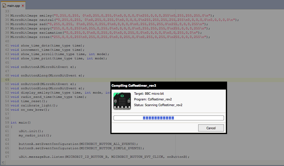
There exists a lot of ways to program the micro:bit, as presented on the board’s website. This blog on the bluetooth goes through them all, and even some additional programming options. We created the first test version of the coffee timer using the Microsoft block editor programming. The editor was surprisingly easy to use, and we quickly whipped up a very brute-force version of the functionality. When moving on, we used the ARM mBed online compiler to create our program. There we have access to the uBit C++ library provided by Lancaster University. The next level would be to scrap all the “high level” API’s, and program the on-board nRF51 Micro controller natively using the SDK provided by its manufacturer Nordic Semiconductor. We did not do this in this project, which led to some compromises being made. More on that in the section about low power wireless using the micro:bit. The image below shows the first mockup version of the code created with the block editor.
Wireless options with the micro:bit
As mentioned, there are several ways of programming the micro:bit device. Because of this, there are several APIs which interface with the built in radio of the nRF51.
- Bluetooth Low Energy (BLE) through Microsoft Block Editor and Microsoft Touch develop.
- Bluetooth Low Energy(BLE) through the uBit class in mBed.
- The uBit.radio interface of the uBit class in mBed.
- The radio API of MicroPython.
- The bluetooth Low Energy(BLE) API in the Nordic nRF5 SDK.
- The Electronic ShockBurst API in the Nordic nRF5 SDK.
- Use the radio hardware directly (propreitary protocol) with the Nordic nRF5 SDK.
The block editor and the rest of the editors intended for kids, offer a simplistic interface to bluetooth. One is easily able to create a wireless remote or similar which can be connected to with a smartphone. It does not allow for direct control of the BLE advertising, which is the way to broadcast data in BLE. This is the method used by for example BLE beacons to broadcast data to its surroundings. Since broadcasts are not available, we could not use these options in this project. As far as we know, there is no option to send generic data either, just predefined things like remote control buttons or camera triggers.
The mBed BLE API seemed to be the way to go, as it allows for direct control over the broadcasting. We created a working implementation using BLE to broadcast the “time since last brew” data. This data could be picked up by any BLE observer devices, like a smartphone. When we started to implement our own BLE observer on a micro:bit, we found out (after a lot of debugging) that the micro:bit does not support the BLE observer role out of the box. Which BLE roles a project supports, is dependant on which BLE stack is compiled into the application by mBed. We know that the nRF51 supports the observer role with the right BLE stack, but it is no obvious way to chance which stack mBed compiles into the application. This is decided by which target is chosen in the mBed online compiler, and probably by a #define somewhere hidden a couple of layers down. It is definitely possible to make the micro:bit support the BLE observer role by fiddling with the target settings, but we decided not to invest even more time into that.
The “radio” classes of both MicroPython and the uBit C++ framework provide very generic radio capabilities. We can send data, as well as set up events which notify us when new data has been received. It is not clear how these transmissions are implemented on a lower level, but we guess that is kinda the point. These radio APIs are not low power, as the devices are always listening for received data in order to notify the program immediately. This is the option we ended up using, simply because it was the easiest to implement, and it worked out of the box. The receiver units are no longer ULP devices, but can last a couple of days on a battery if need be. We currently power ours with USB power, or a USB power bank if we need to move it around.
When using the last three methods (nRF5 SDK), we are treating the micro:bit as any other nRF51 device, and hence we lost all the nice micro:bit libraries for using the buttons, LED matrix, accelerometer and magnetometer. All of this is still available to us, but we must write our own drivers. The main reason for choosing these options are to gain complete control over what is happening, and to be able to implement a ULP solution to the problem. It must be said that the nRF5 SDK is in a totally different league in terms of complexity and size compared to the other options mentioned. One is only able to benefit from this option by knowing the SDK from other projects, or be prepared to spend time to learn about the nRF5 ecosystem. We did not experiment with this option in this project, based on the time it would take to write the drivers for the micro:bit hardware like the LED matrix. In hindsight, we probably should have started here instead of spending a lot of time making mBed BLE work.
When using Bluetooth Low Energy (BLE) , most approaches make it easy to make a BLE peripheral device, i.e a device which typically connects with a smartphone or laptop. For communication between two micro:bits, the proprietary protocols of the uBit class and the microPython framework work well, but do not provide options for low power operation. Treating the micro:bit like any nRF51 device will give full customizability, but with a significant increase in complexity.
Enclosures
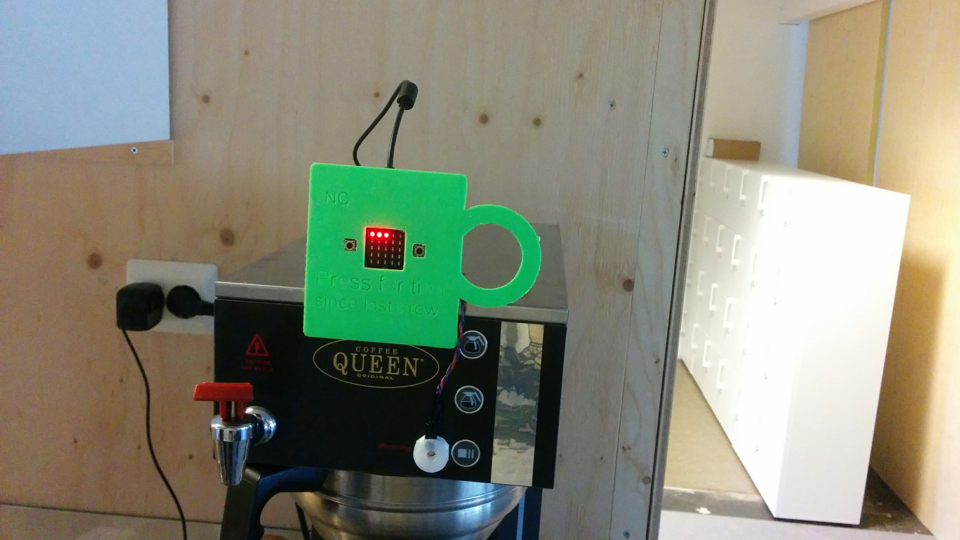
The timer device
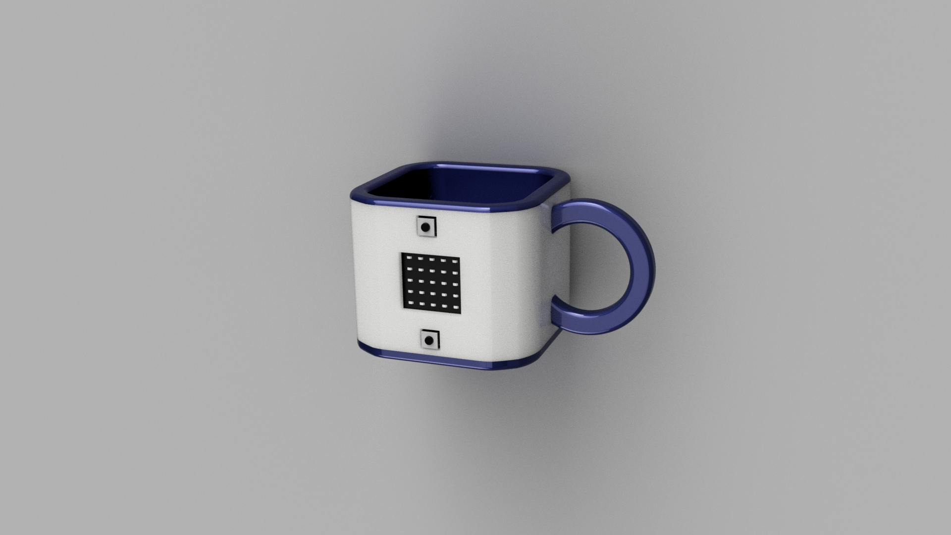
For the timer device mounted on the coffee maker, we wanted a design showing that the information on the screen was coffee related. We considered coffee beans coffee pots, but landed on making it look like a coffee mug. The first edition had a coffee mug front plate, but it was not very good-looking. It had the USB-cable sticking out on top, and was also very prone to fall apart when using it.
The new design had to be more three-dimensional, and be more aesthetically pleasing. When creating a normal coffee mug shape, two problems became apparent:
- The micro:bit has a flat front with a screen and buttons that must be visible and accessible.
- The micro usb connector is placed on the side of the board, making it impossible to hide the usb cable when having the board in the front.
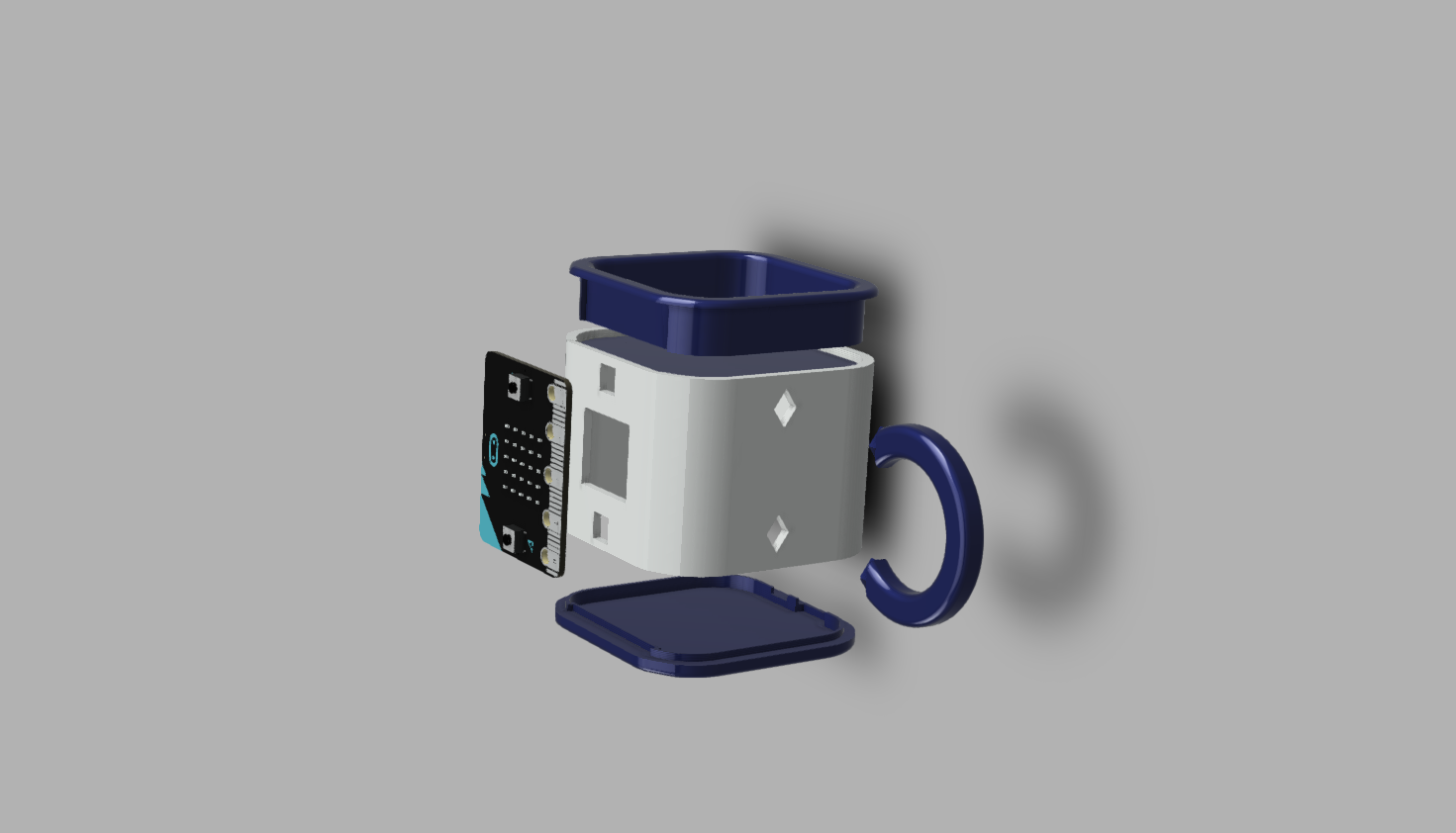
Instead of making the mug round, it was designed as a square block with rounded edges. This made for a coffee mug look, but with a flat front.
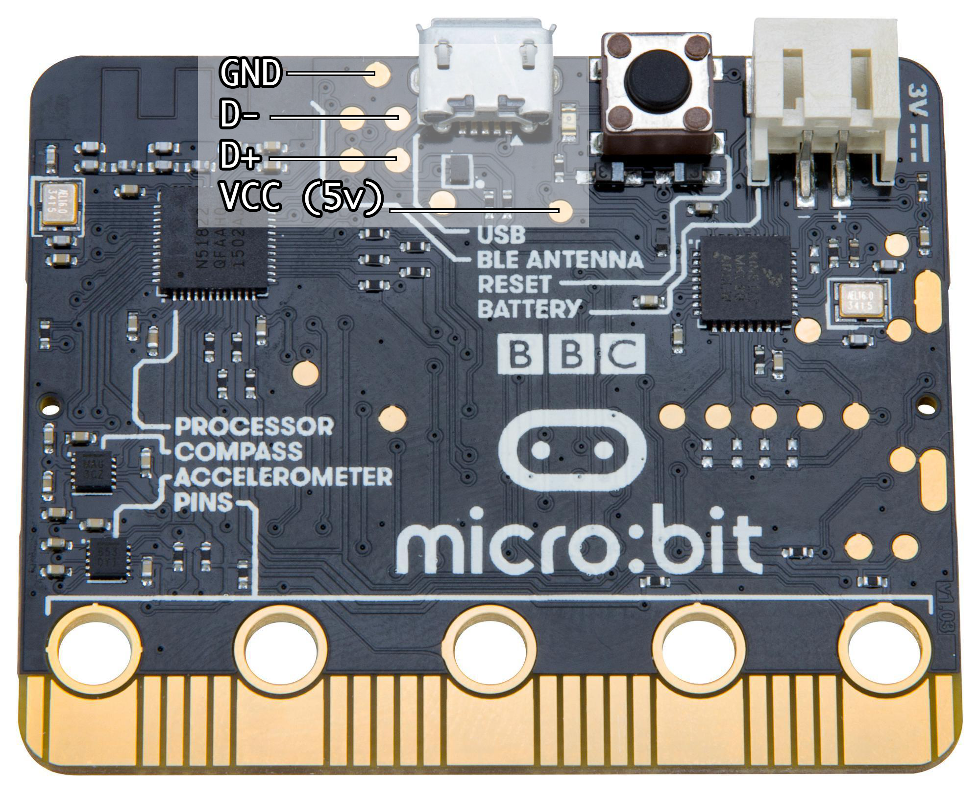
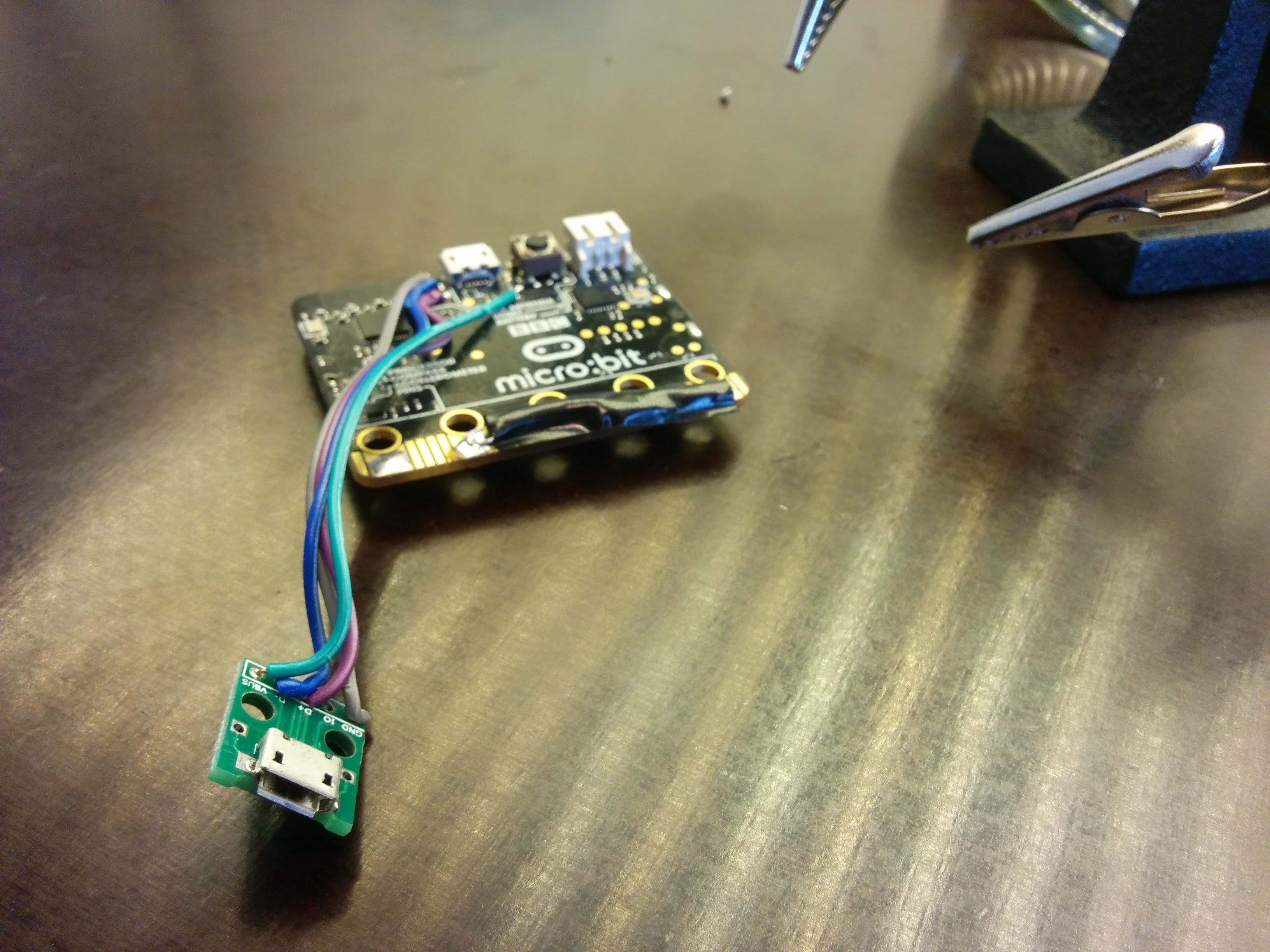
The usb connector problem was solved by connecting another micro USB connector with some wires. It was soldered to the pads on the backside of the micro:bit. See the image below to see which pad is what. The correct pads were discovered by measuring with a multimeter. The new usb connector could then be placed where we wanted it, which was on the backside of the mug.
When designing an enclosure for the micro:bit, it is important that its back is supported. If not, the board will be pushed in when someone pushed the buttons on the front. At the same time, it must be possible to insert and take out the micro:bit from the enclosure. These two demands are conflicting, and needs a creative solution. In the first version, the board is put into a holder, and then a front cover was mounted in front of it. This ensured both back support and access to the buttons, but is was not pretty nor very practical. In the final version, this was solved in a more elegant way. The inside of the mug had holes for the micro:bit buttons and screen, and it could be fitted in from the inside. The micro:bit was held in place with the bottom and top lids, which could be removed.
The receiver devices
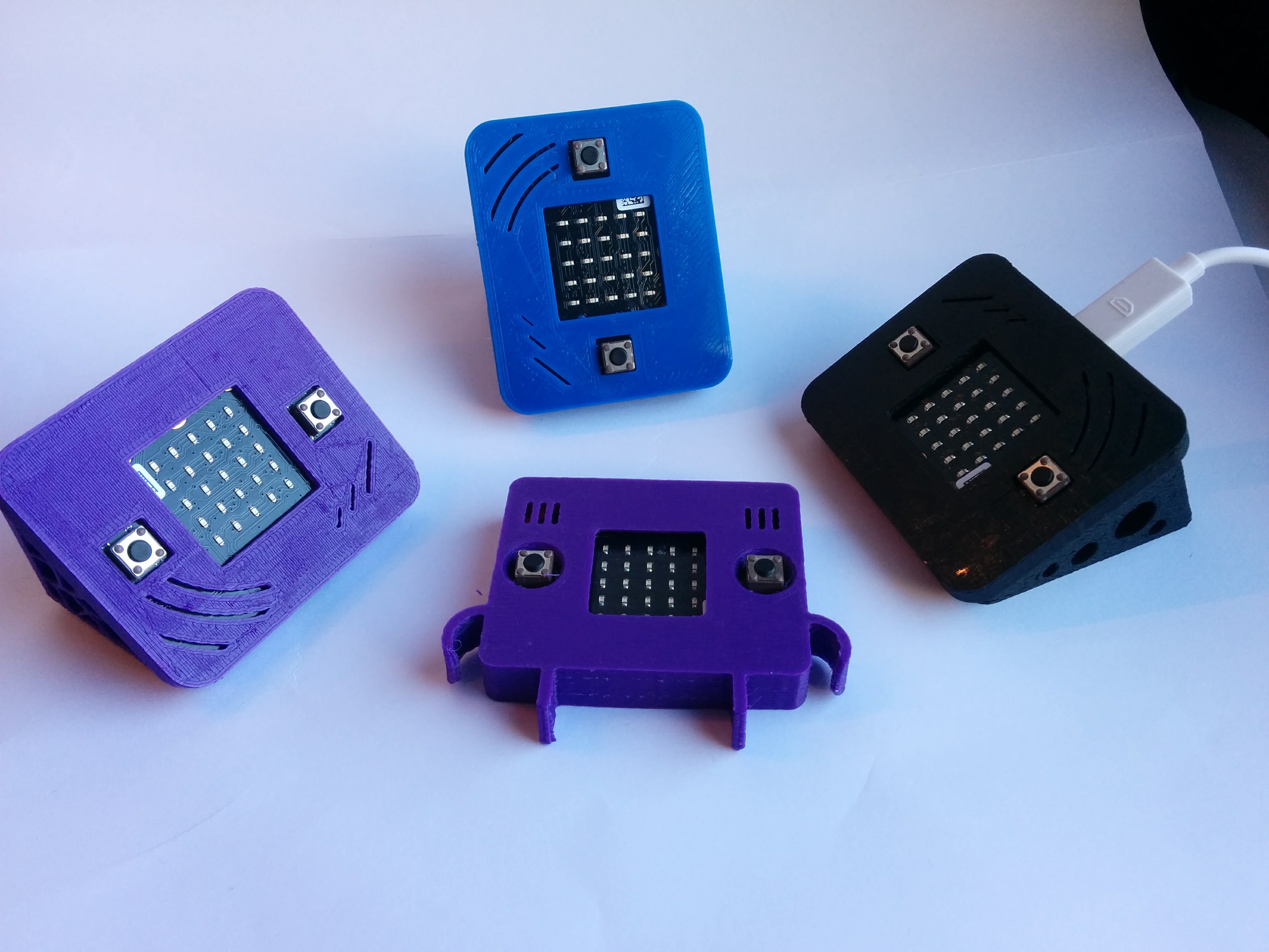
The receiver devices are small micro:bit devices for use on the desks around the office. They alert users when new coffee is made, and will also show the time since last brew when the buttons are pressed. We created a couple of different enclosures for these devices, to find out what worked best.
The most basic version was not event made by us, it was found on thingiverse. It is a very cool micro:bit cover made by Craftyrobot.
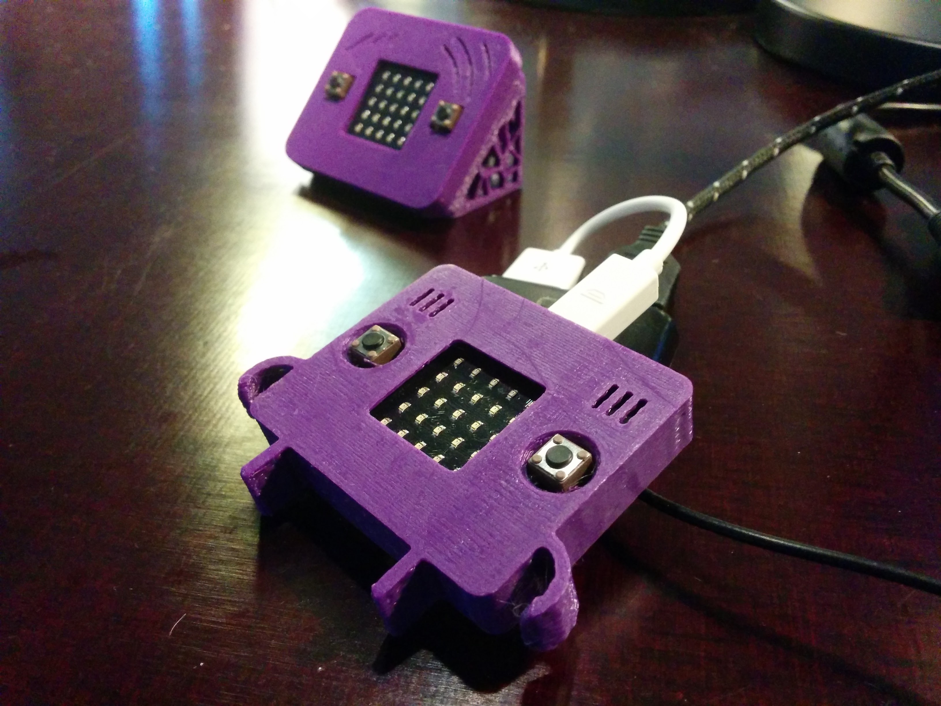
In the second and third version, the micro:bit was mounted at 45 degrees, so that the screen is visible when it is laying on a desk. One was sitting horizontally on the desk, and the other one vertically. They were made up of two parts, the base and the cover. They got some artistic cutouts in the base using a voronoi sketch generator plugin in Fusion 360. These two designs had one common flaw; They were very unstable, and would sometimes flip over or move when the buttons were pushed. The fourth version had a more flat design, as well as a bigger and more stable base. This design gave a lot more stability, as well as a better angle on the usb cable sticking out.
The STL files for everything 3d-printed in this project can be downloaded here.