

1.Profile During connection procedure of BLE, there are three packages: SCAN_REQ, SCAN_RSP 和 CONNECT_REQ。 SCAN_REQ: Scan request, issued by MASTER DEVICE, send to SLAVE DEVICE,sent by the Link Layer in the Scanning State, received by a Link Layer in the Advertising State. SCAN_RSP: sent by the Link Layer in the Advertising State, received by a Link Layer in the Scanning State, it's another function is as a complement of advertising data, slave device could transfer more advertising data to master device, for example, device name could be inside this package instead of advertising package. CONNECT_REQ:Issued by master device. This PDU is sent by the Link Layer in the Initiating State and received by the Link Layer in the Advertising State。Once slave device received this PDU, the connection will be set immediately and enter connection state (master device and slave device will exchange effective PDU or empty PDU. Detail description see below
2.Keywords:Hollong BLE Sniffer,BLE analyzer,BLE data acquiring, BLE Data Analyzer,BLE Capture
3.Preparation before capturing BLE data
- Hardware:One BLE device (as slave device) and one master device(such as lightblue or redwoods app in iOS or Android); One HOLLONG BLE SNIFFER
- Software:Hollong BLE sniffer and protocol analyzer download link:
http://www.viewtool.com/index.ph ... hollong-4-0-4-1-ble
- SCAN_REQ PDU
1)Complete data
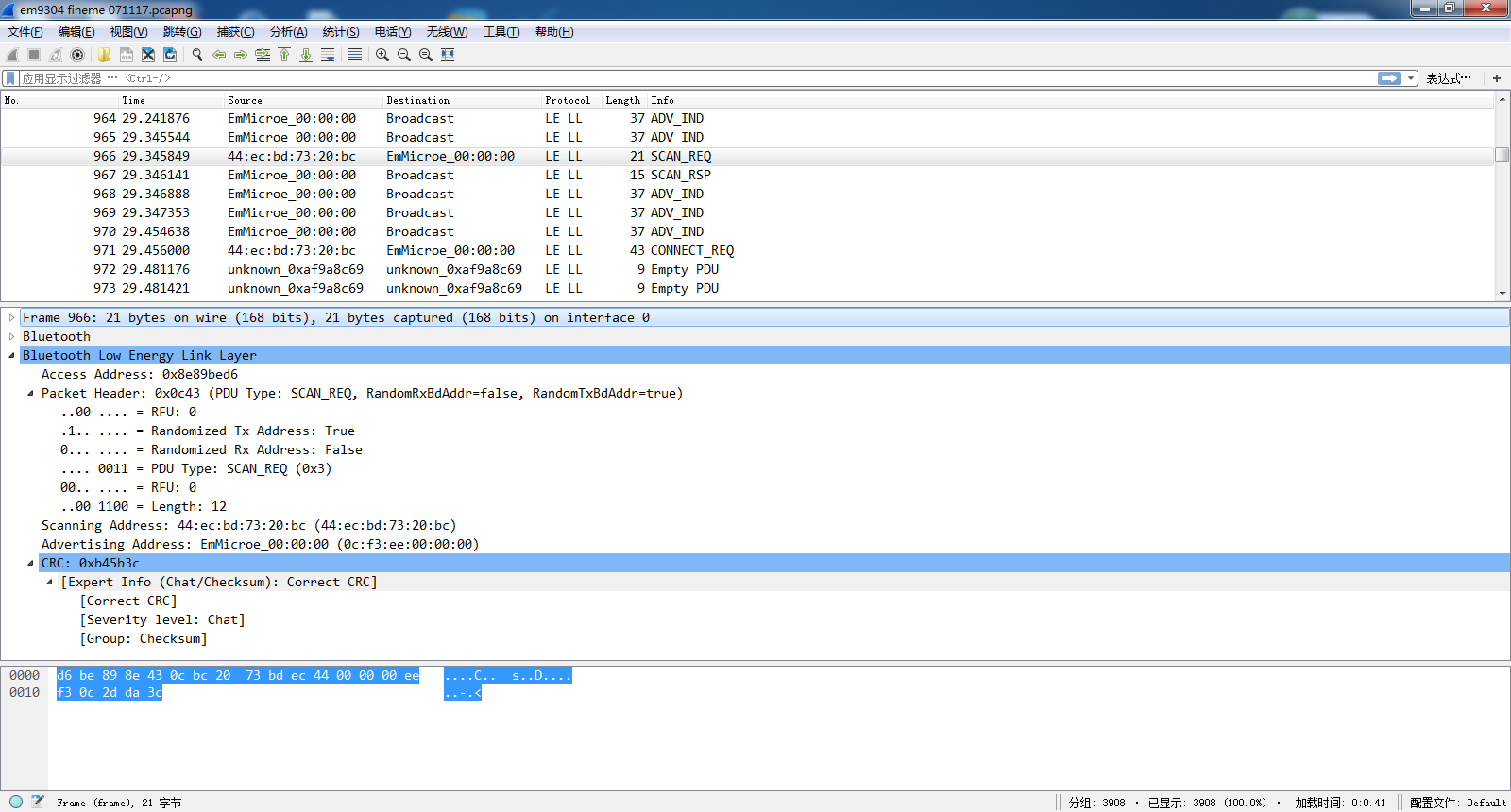
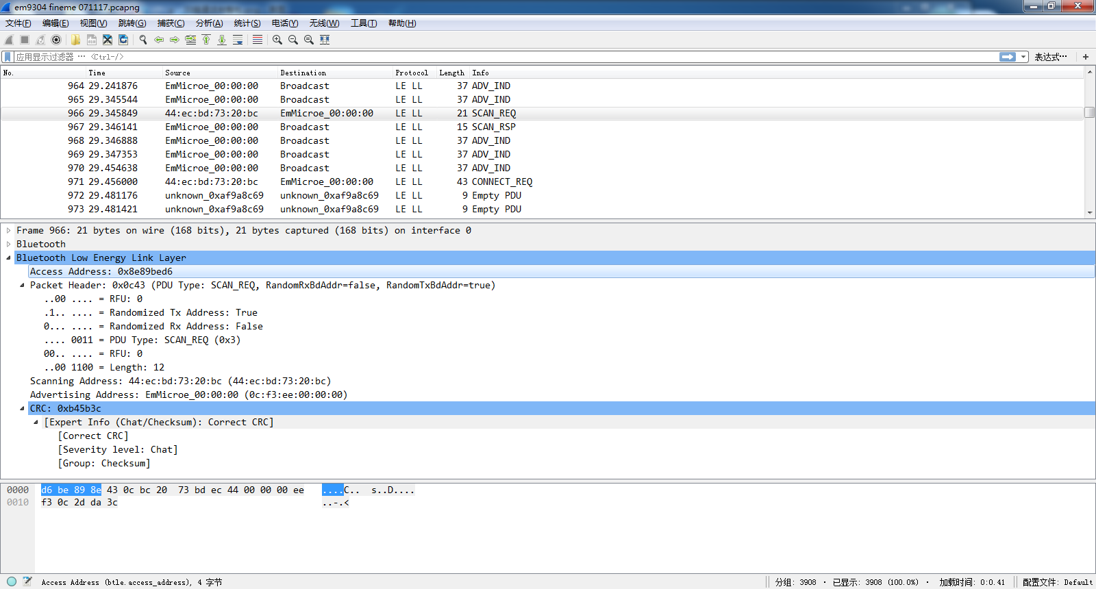
- Access Address: for advertising PDU, it is fixed length (4 bytes) and fixed contents(0x8e89bed6) which master and slave device could be addressed.
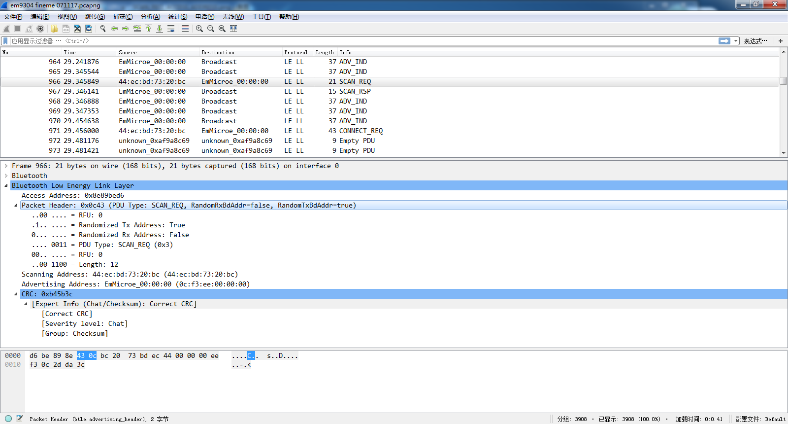
 3) Header Info: fxied (2 bytes):used as 16 bites
BIT[0:3]:advertising PDU type:
3) Header Info: fxied (2 bytes):used as 16 bites
BIT[0:3]:advertising PDU type:
    PDU Type
    b3b2b1b0 Packet Name
    0000 ADV_IND: connectable undirected advertising event
    0001 ADV_DIRECT_IND:connectable directed advertising event
    0010 ADV_NONCONN_IND:non-connectable undirected advertising event
    0011 SCAN_REQ:scan request
    0100 SCAN_RSP: scan response
    0101 CONNECT_REQ:connection request
    0110 ADV_SCAN_IND:scannable undirected advertising event
    0111-1111 Reserved
BIT[4:5]:Reserved BIT[6]:RxAdd BIT[7]:TxAdd BIT[8:13]:advertising data length (Maximum 37 bytes) BIT[14:15]:Reserved
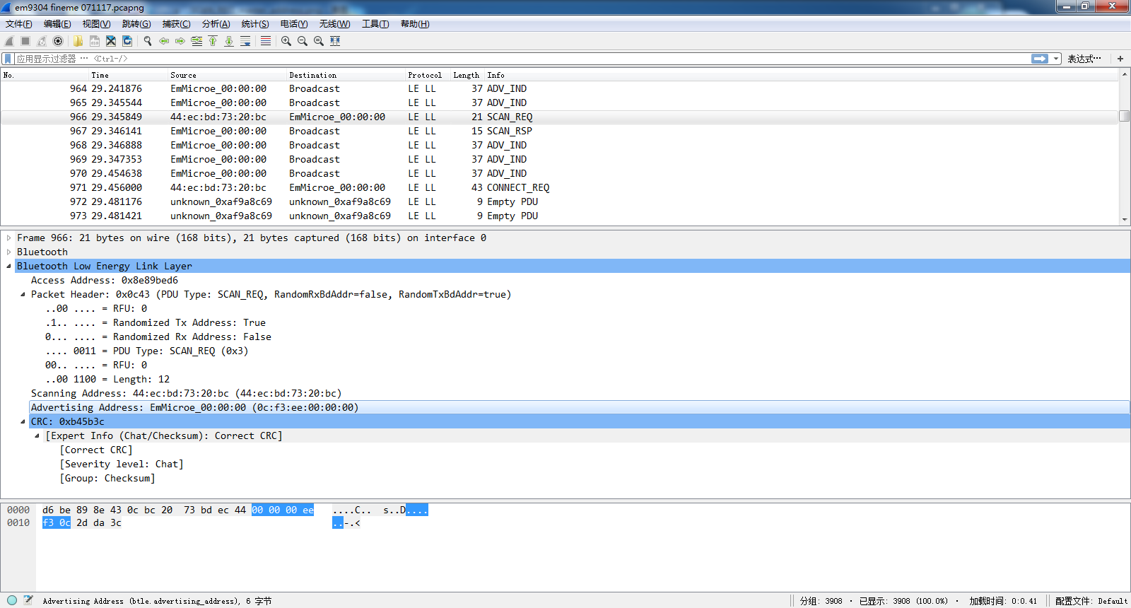
 4) Master device address
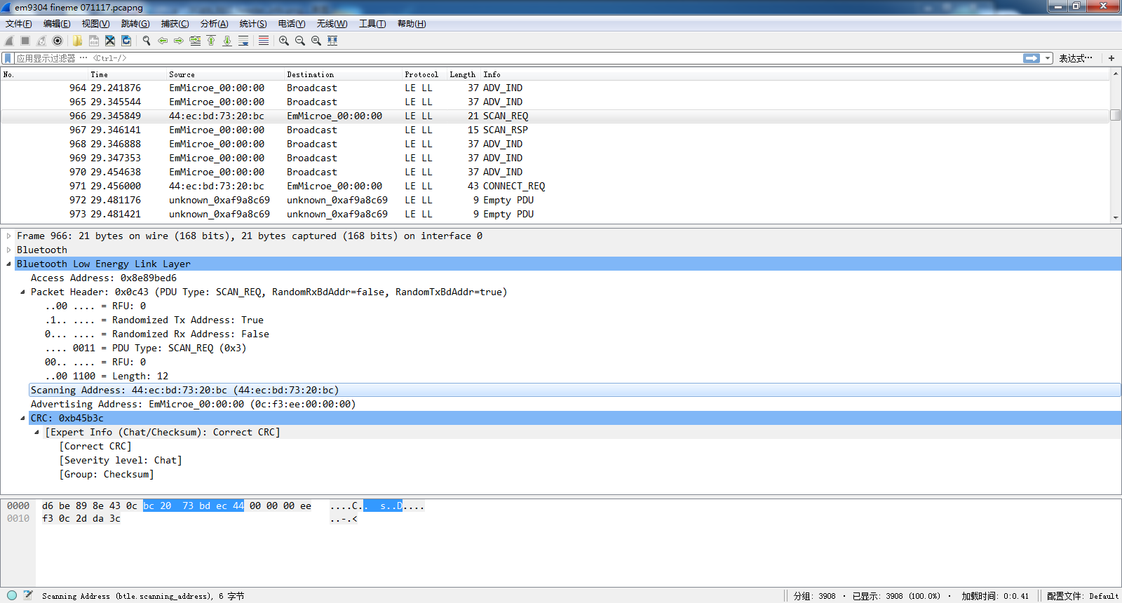 5) Slave device address
6)CRC
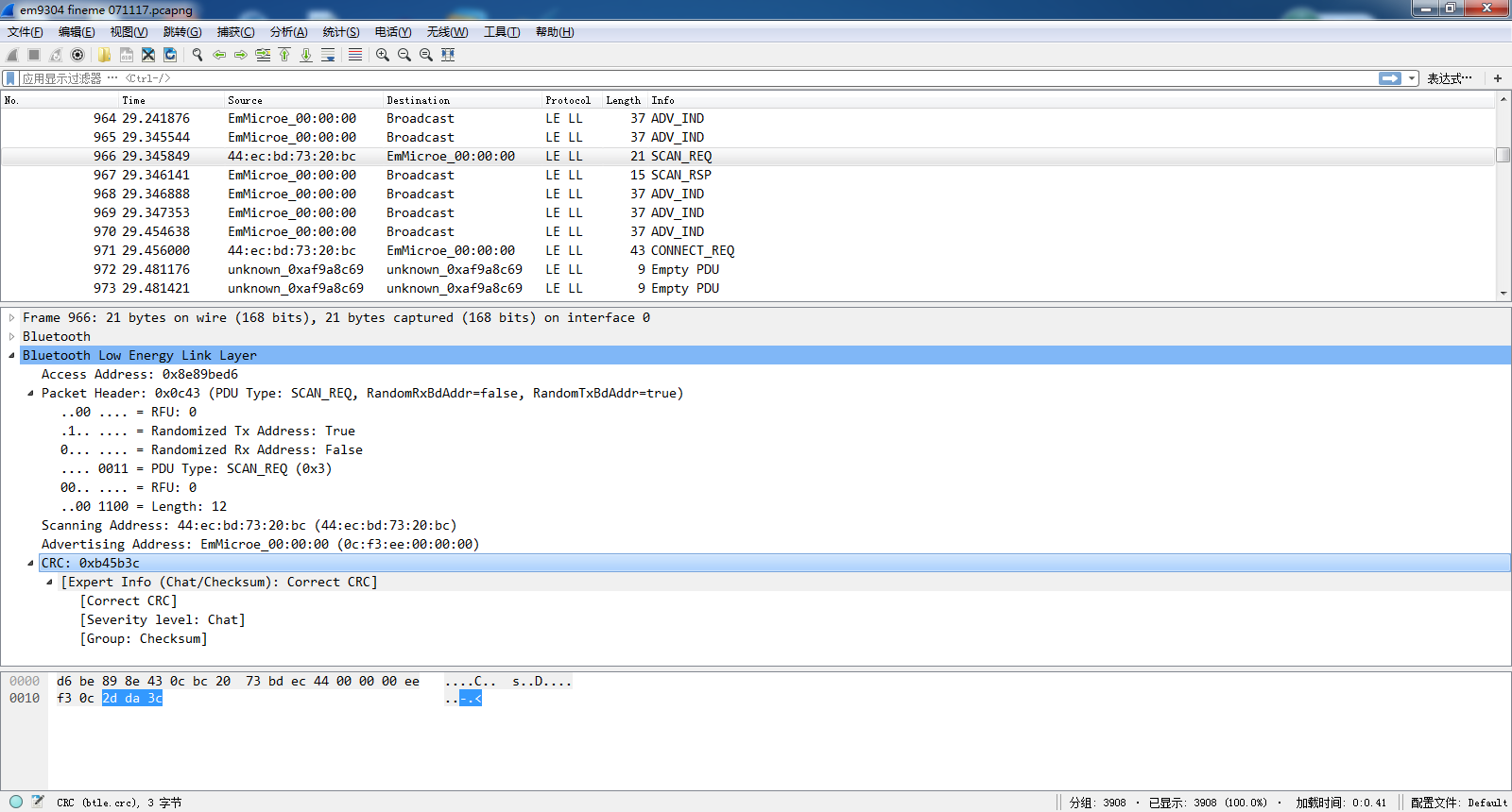
-
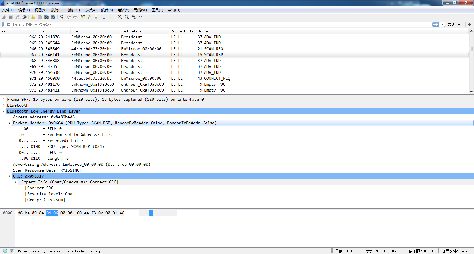
SCAN_RSP PDU 1)Access Address same definition as above
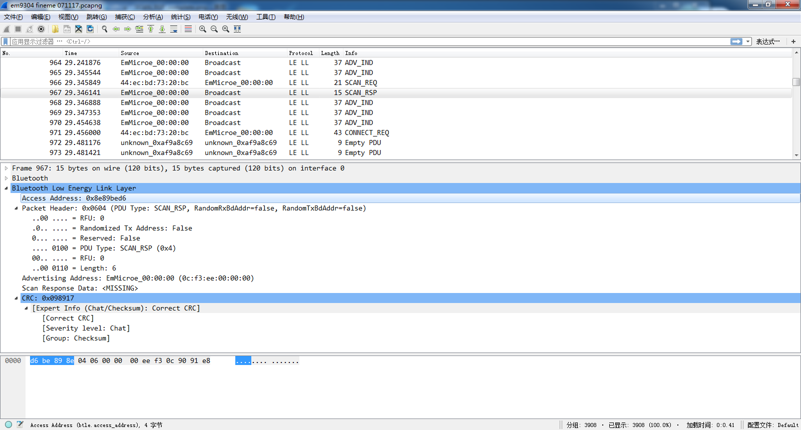
2)Header Info same definition as above
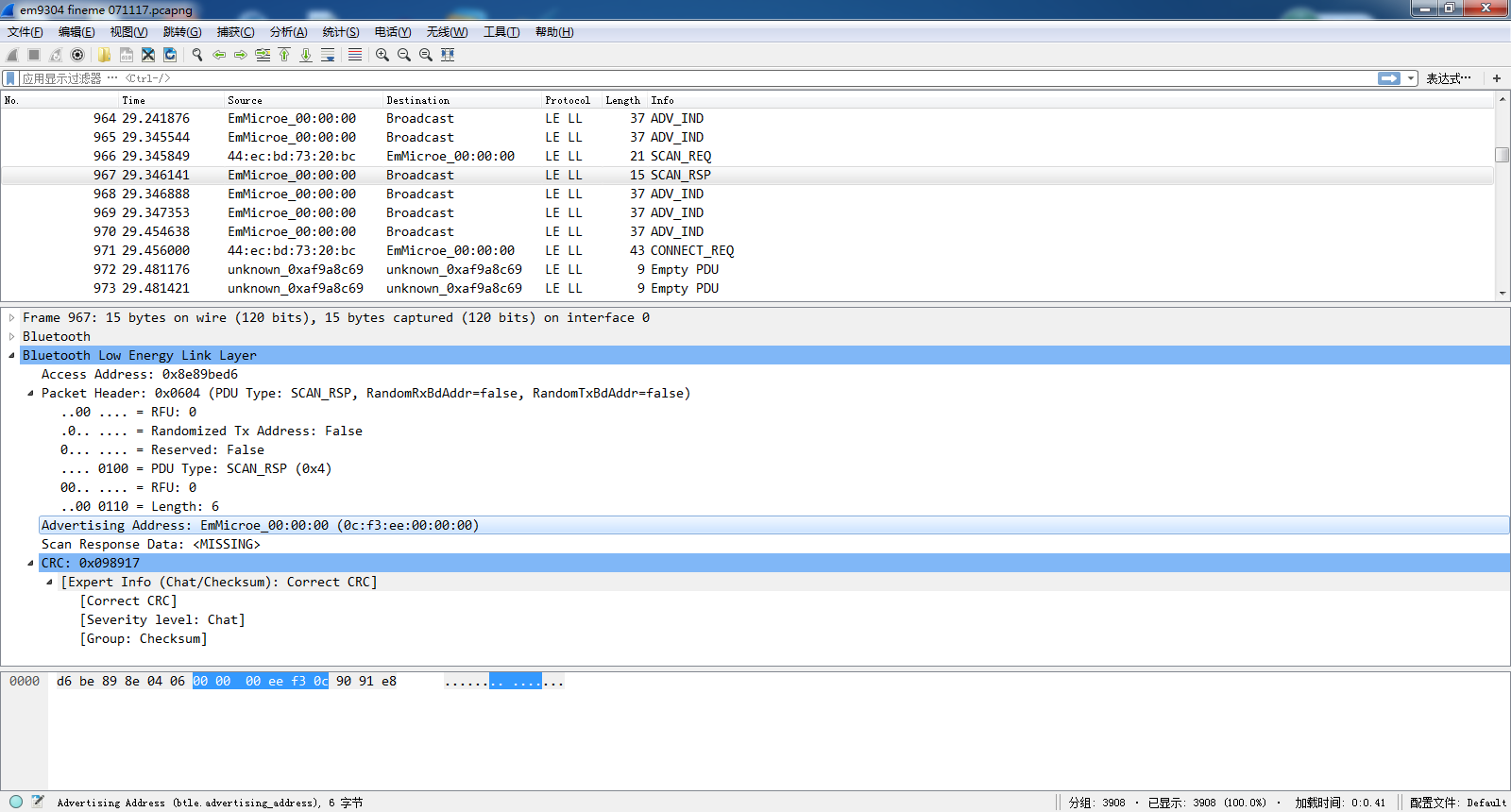
3)Slave device address MAC ADDRESS: fixed 6 bytes.
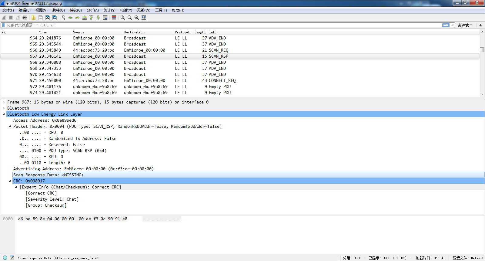
4)Response data(complement of advertising data) same format as advertising data, detail please see:
http://www.viewtool.com/forum/vi ... &extra=page%3D1 in this example, there is no data for complement of advertising data
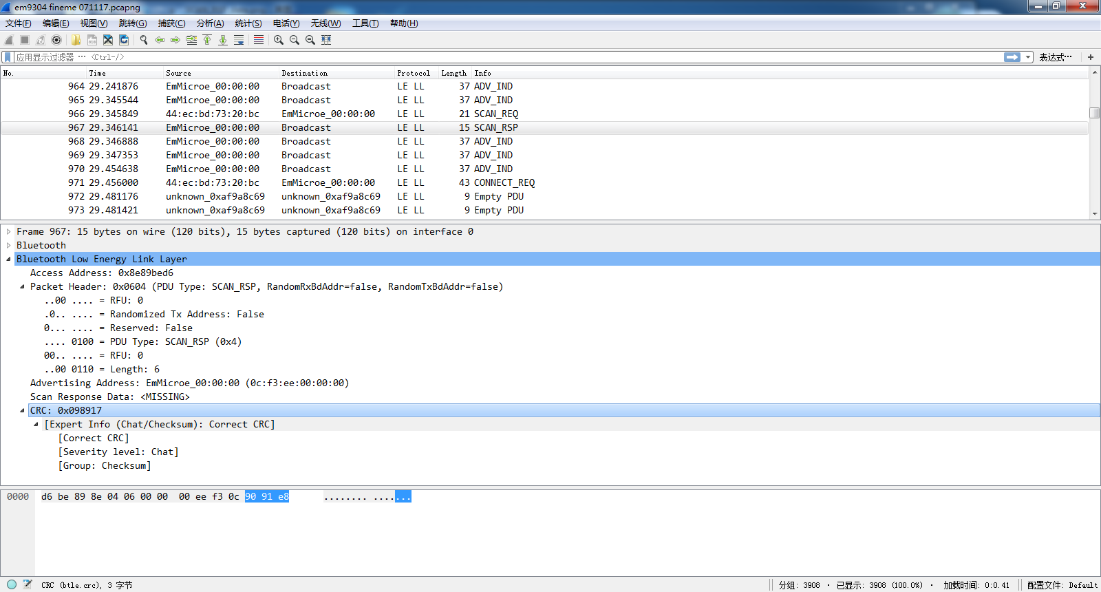
5)CRC
Fixed 3 bytes
 5. CONNECT_REQ PDU
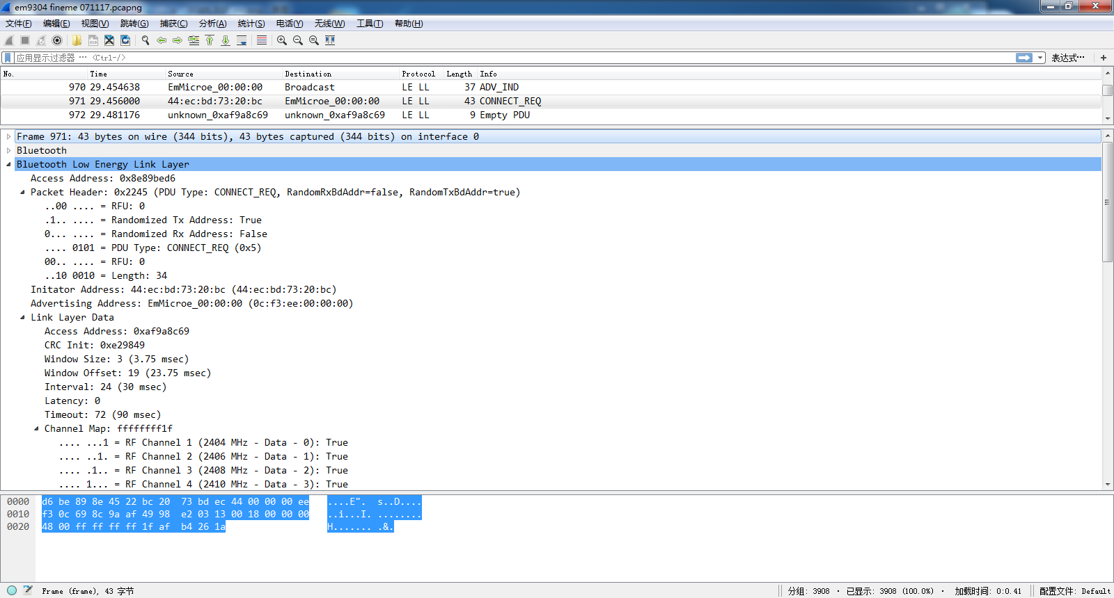
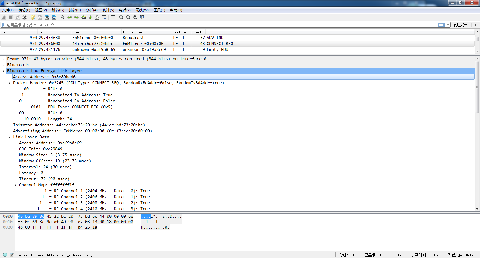
 1)Access Address
  Fixed length (4 bytes) and contents (0x8e89bed6).
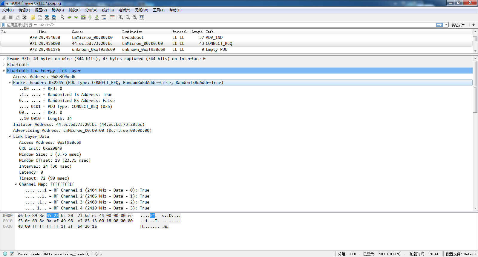
2)Header Info
      same definition as above
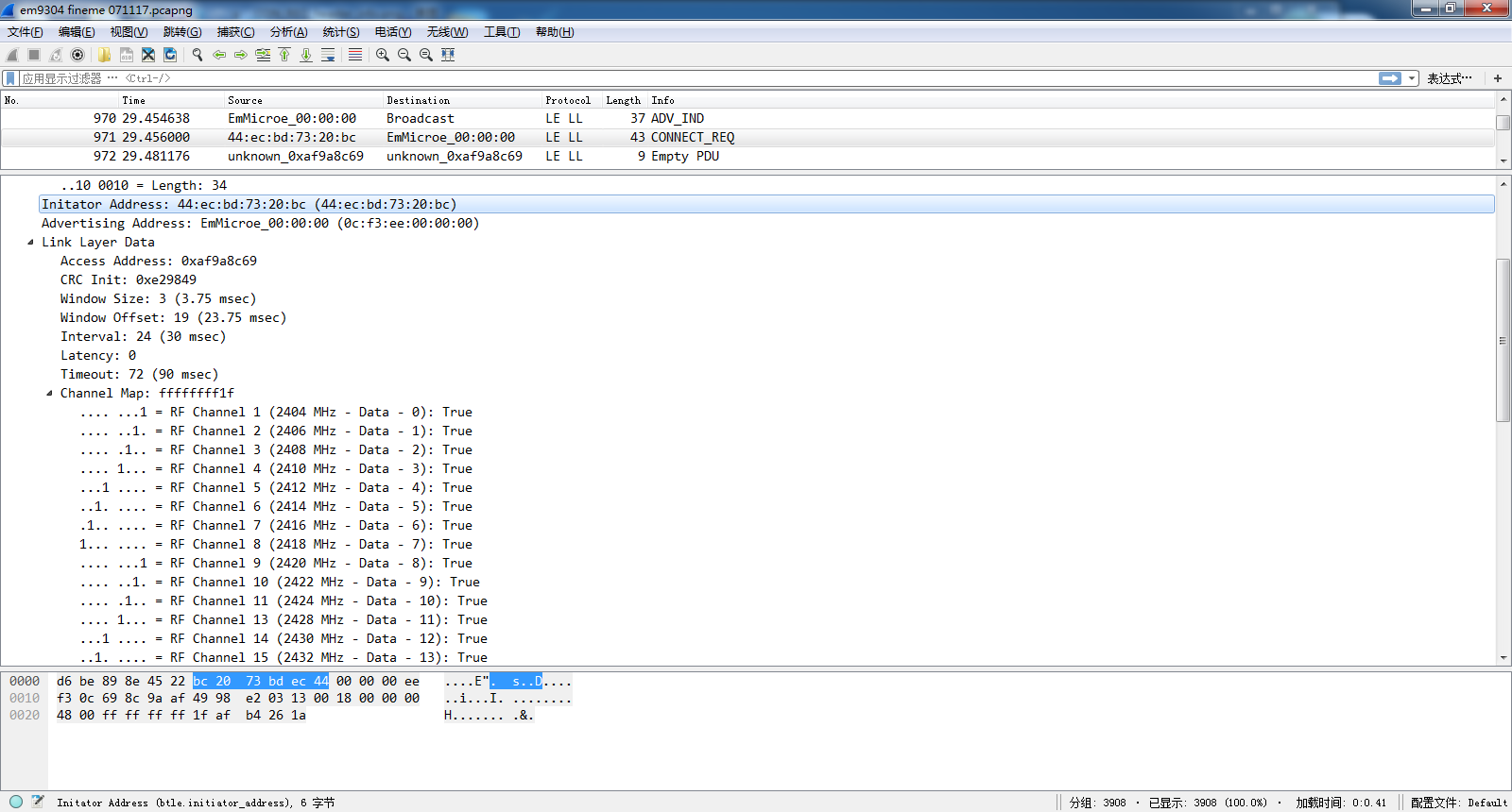
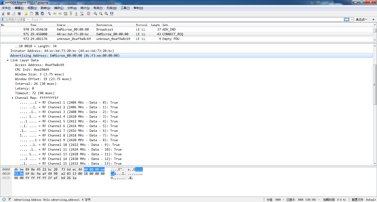
3)Master device address
4)Slave device address
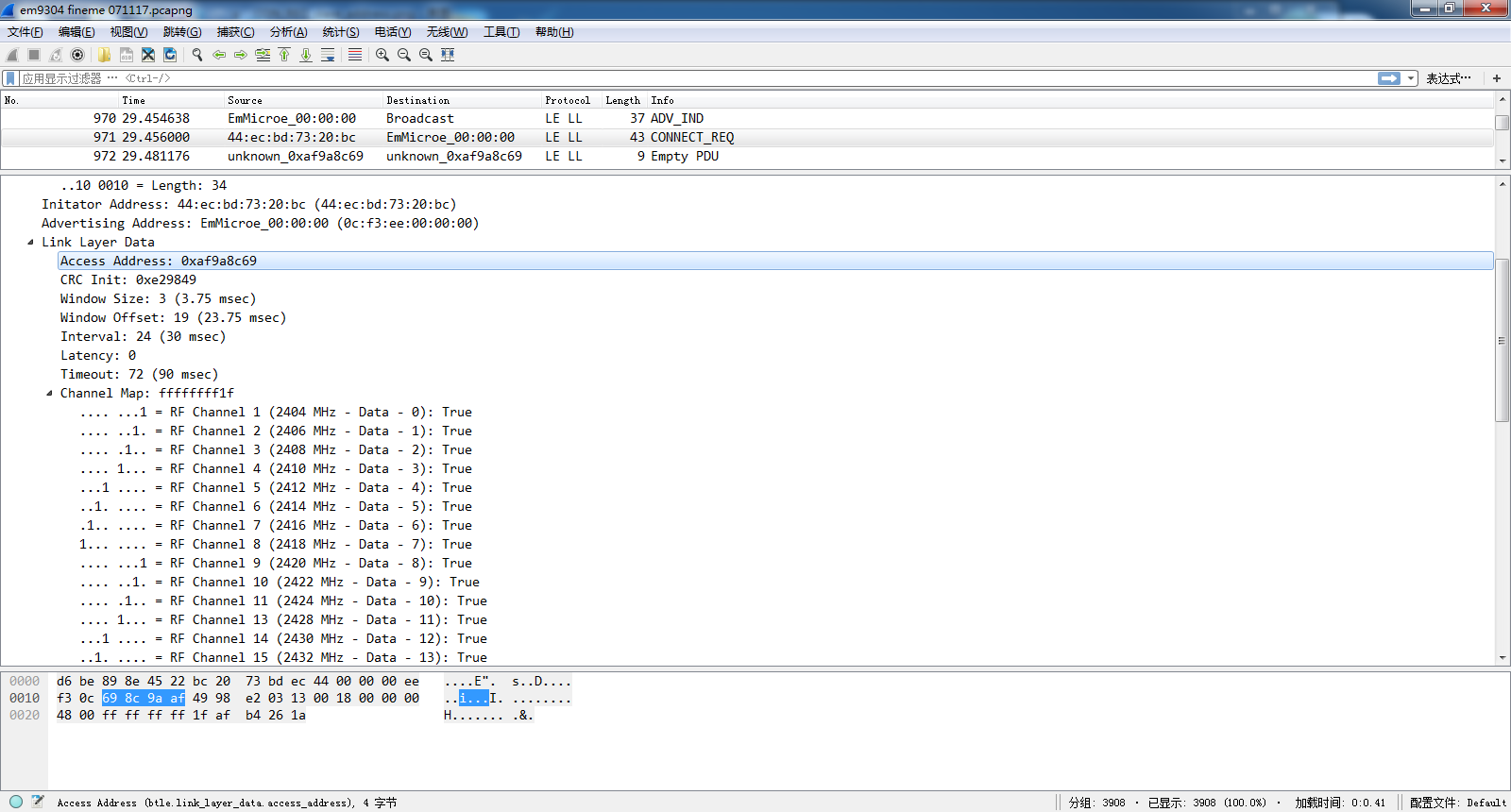
5)Access Address
used after connection setup(BLE data channel),this address has been assigned by master device, fixed length(4 bytes) but not fixed address (not like advertising PDU access address has fixed address(0x8e89bed6))
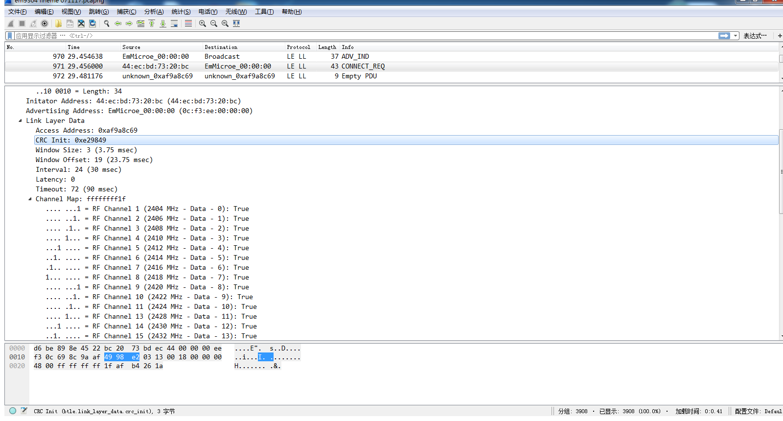
6)CRC INIT
CRC value for initializatoin,used for CRC data verification
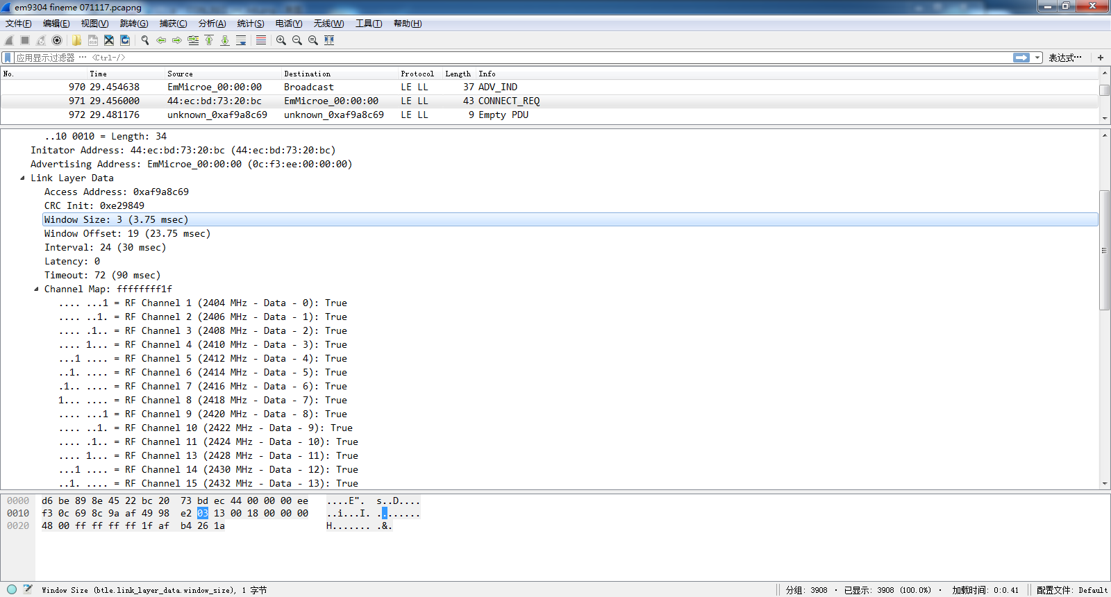
7)Window Size
The WinSize field shall be set to indicate the transmitWindowSize value, as defined in Section 4.5.3 in the following manner: transmitWindowSize = Win-Size * 1.25 ms.
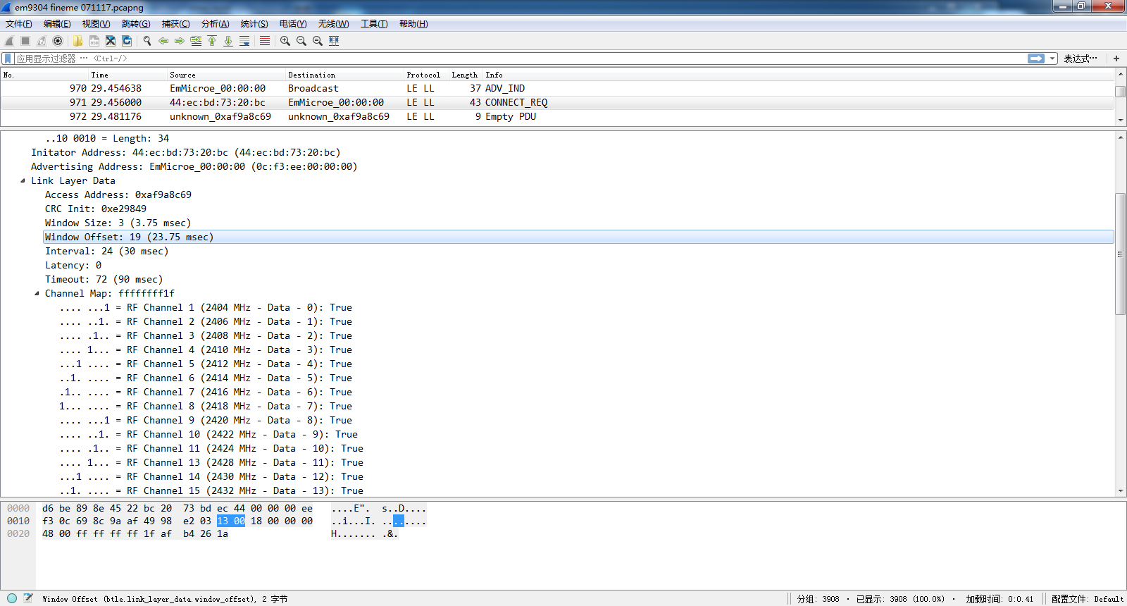
8) Window offset
The WinOffset field shall be set to indicate the transmitWindowOffsetvalue,as defined in Section 4.5.3 in the following manner:.transmitWindowOffset = WinOffset * 1.25 ms.
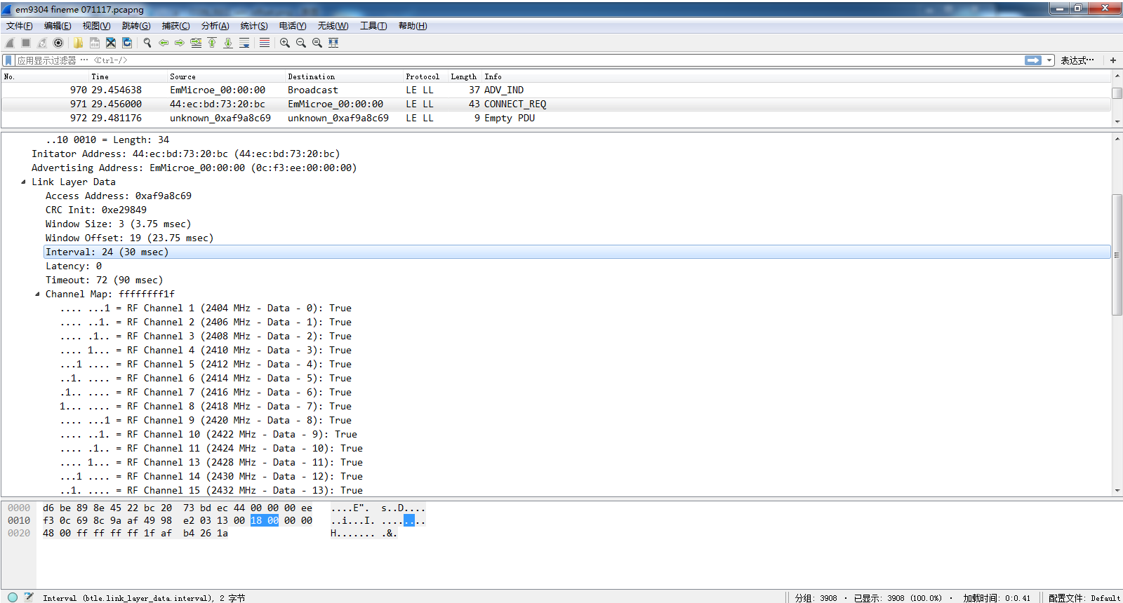
9)CONNECTION INTERVAL
The Interval field shall be set to indicate the connInterval as defined in Section 4.5.1 in the following manner:connInterval = Interval * 1.25 ms
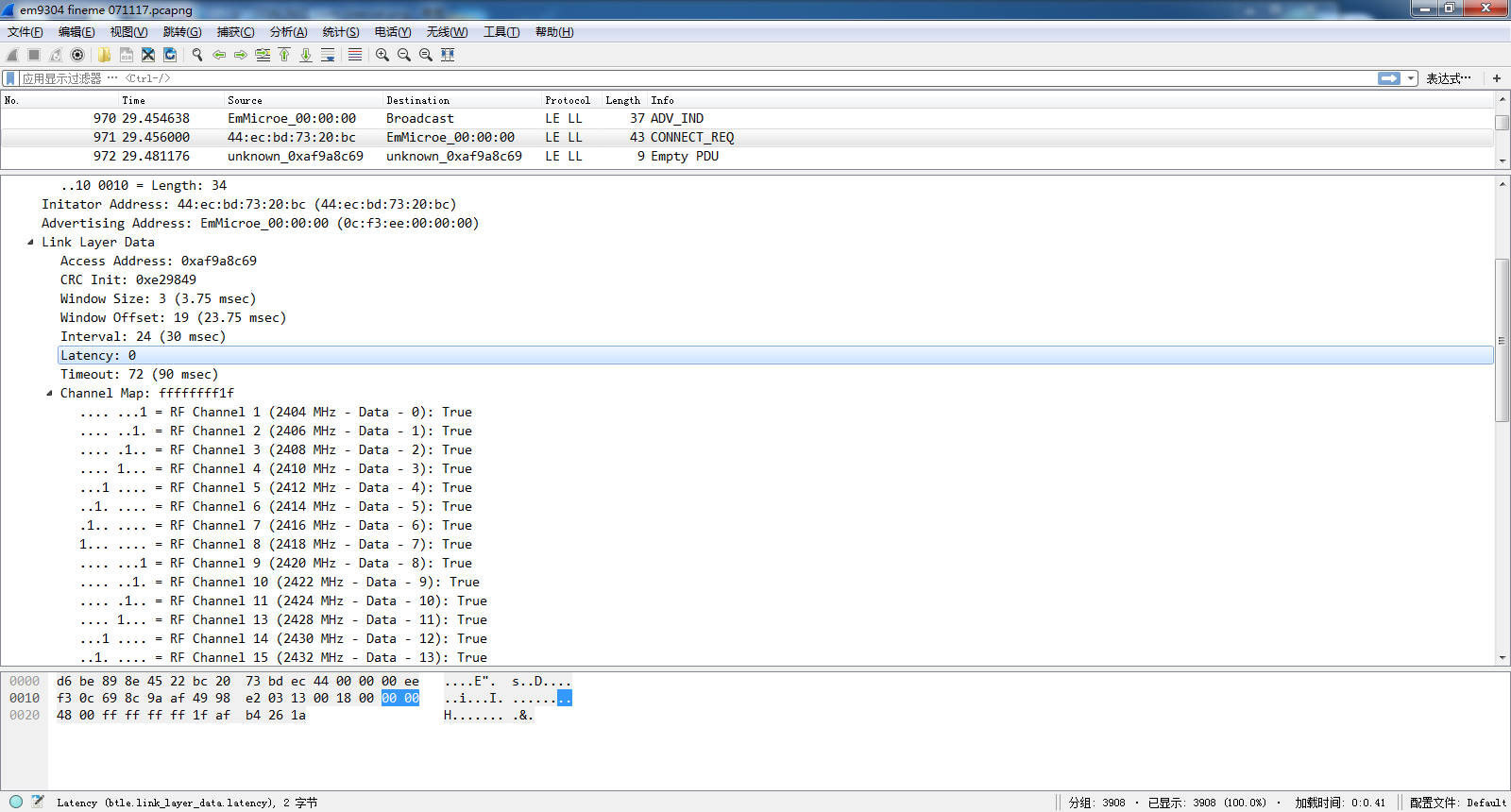
 10)Latency
The Latency field shall be set to indicate the connSlaveLatencyvalue, as defined in Section 4.5.1 in the following manner: connSlaveLatency = Latency.
10)Latency
The Latency field shall be set to indicate the connSlaveLatencyvalue, as defined in Section 4.5.1 in the following manner: connSlaveLatency = Latency.
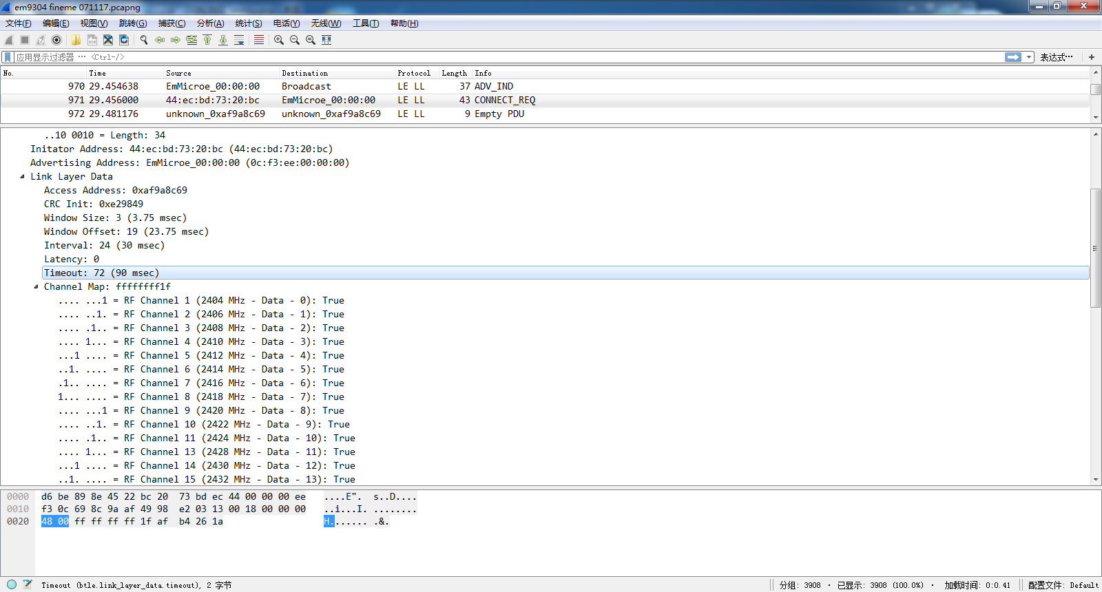
   11) Maximum Connection Time Out
       The Timeout field shall be set to indicate the connSupervisionTimeoutvalue,as defined in Section 4.5.2, in the following manner: connSupervisionTime- out = Timeout * 10 ms
      Either of master or slave not receive data (include empty data) over above timeout,device will turn connection to non-connection state(master device is available scan device again, slave device is also available to do advertising again, all up to application).
      The timeout = TIME_OUT * 10MS, here it is:72 (0X48) * 10 = 720 MS, that means, either master or slave not receive data over 0.72s, then connection state will be terminated.
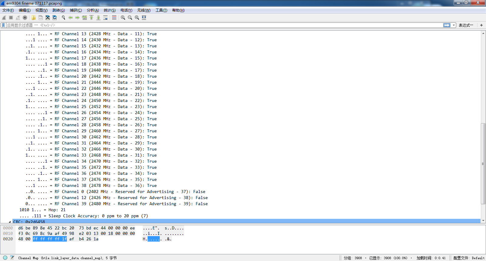
 12)CHANNEL MAP
The ChM field shall contain the channel map indicating Used and Unused data channels. Every channel is represented with a bit positioned as per the data channel index as defined in Section 1.4.1. The LSB represents data channel index 0 and the bit in position 36 represents data channel index 36. A bit value of ‘0’ indicates that the channel is Unused. A bit value of ‘1’ indicates that the channel is Used. The bits in positions 37, 38 and 39 are Reserved for Future Use. Note: When mapping from RF Channels to data channel index, care should be taken to remember that there is a gap where the second advertising channel is placed.
The Hop field shall be set to indicate the hopIncrement used in the data channel selection algorithm as defined in Section 4.5.8.2. It shall have a random value in the range of 5 to 16。
12)CHANNEL MAP
The ChM field shall contain the channel map indicating Used and Unused data channels. Every channel is represented with a bit positioned as per the data channel index as defined in Section 1.4.1. The LSB represents data channel index 0 and the bit in position 36 represents data channel index 36. A bit value of ‘0’ indicates that the channel is Unused. A bit value of ‘1’ indicates that the channel is Used. The bits in positions 37, 38 and 39 are Reserved for Future Use. Note: When mapping from RF Channels to data channel index, care should be taken to remember that there is a gap where the second advertising channel is placed.
The Hop field shall be set to indicate the hopIncrement used in the data channel selection algorithm as defined in Section 4.5.8.2. It shall have a random value in the range of 5 to 16。
  13) HOP 及CLOCK
   0xAF (10101111)
   HOP: 10101
CLOCK: 111 => the crystal precision is 为0-20PPm
The first 5 bits is used for HOP algorithm(HOPINCREMENT),another 3 bits is for crystal accuracy(how many PPM)
SCA masterSCA,
000: 251 ppm to 500 ppm
001: 151 ppm to 250 ppm
010: 101 ppm to 150 ppm
011: 76 ppm to 100 ppm
100: 51 ppm to 75 ppm
101: 31 ppm to 50 ppm
110: 21 ppm to 30 ppm
111: 0 ppm to 20 ppm
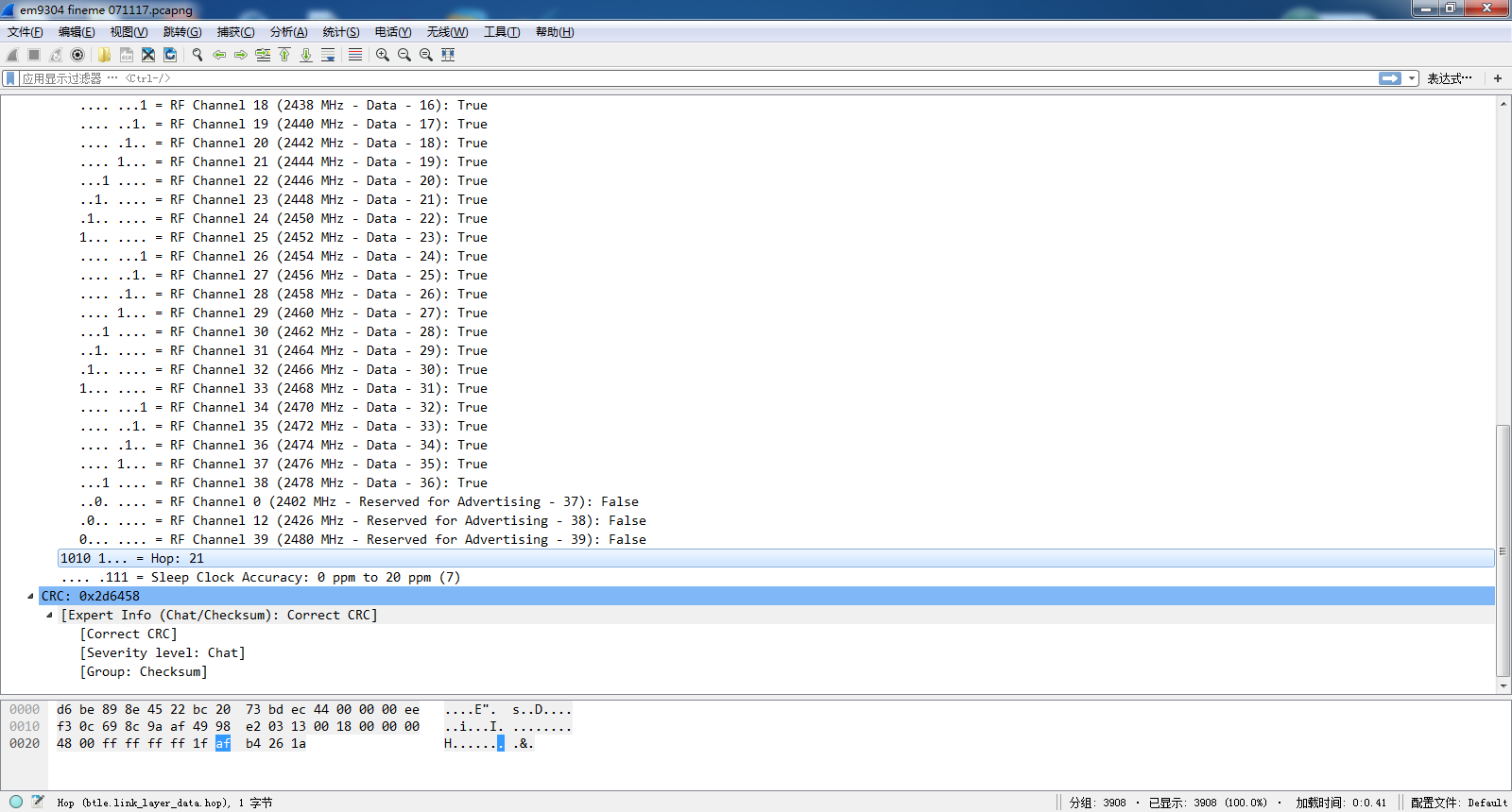
 14)CRC
  Fixed 3 bytes
Get complete Hollong BLE Sniffer captured data file:
Get BLE4.0 specification:www.viewtool.com
Article source:
