


The challenge
As a product is getting into the production phase, the need of a fast and standalone screening facility on the production line arises. Here I'm introducing a production screening setup based on Bluetooth Direct Test Mode (DTM).
What a Production Screening is ... and is not ...
A production screening is a rapid screening process sorting out those units which are not functioning because of manufacturing issues, such as cold soldering, usage of incorrect materials, usage of bad materials, etc.
A production screening is NOT a functional test which correctness of the application functionality is verified. Functional tests must be completed to satisfaction before getting into production phase. If you found that you start talking about testing a function of your application on the production line, it is a strong signal that you may be wandering off somewhere else ...
The Criteria
Throughput
- A production screening shall be completed in a very short period of time. In a typical mass production line, up to hundred thousands of units are churned out in a day. Any extra time taken on screening per unit gets amplified and reduces throughput substantially. Therefore, the screening time per unit shall be minimized.
Scalability
-
The screening station shall be simple and easy to operate by any worker on the production line. Without the need of workers with special skills, the production line can be scaled up to increase the total capacity.
-
Ideally, the screening station should be a portable jig without attaching to any other equipment, e.g. PC. A standalone station which is relatively simple and low cost to duplicate allows the production line be scaled up to increase the total capacity.
Direct Test Mode
Background
DTM is a part of the Bluetooth Core Specifications. It is a special mode for RF PHY testing of Bluetooth low energy devices. To ensure interoperability on signal level, this test is mandatory for certification by Bluetooth SIG.
Upon successful completion of a test in DTM successfully, the unit under test is:
-
Operational: The piece of hardware is able to execute an application, i.e. DTM, which means that there is not any issues on the chip, PCB board and external components which render the board unusable
-
Satisfactory RF performance: The RF performance of the board meets the packet error rate (PER) requirement
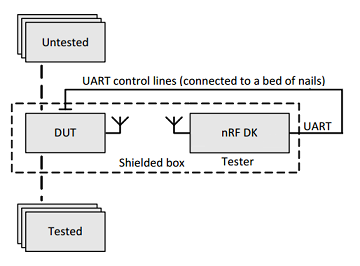
The setup
The picture above shows a setup with two nRF51 DK boards. The boards are connected by a coaxial cable with attenuators to prevent the receiver from damage by strong signal from the transmitter. The boards are put in separate shield boxes to isolate them from ambient RF interference. Each of the boards is connected to the PC through a separate UART so that the PC can send commands to carry out the test in a coordinated manner. The DTM firmware on the boards responds to commands from UART. The firmware on the boards is identical and the test script on PC is the driver of the test.
The frame format of command and event over UART
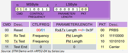
The picture above shows the commands and frame format over UART. The DTM is simple in a way that it supports a set of 4 commands in total. There are further options for the TX test and RX test which includes frequency, packet length and packet type. These commands are sent from the PC to both of the boards.
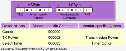
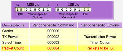
The picture above shows a special frame for vendor specific commands. When the command is TX_TEST 10b and the PKT_TYPE is 11b, the rest of the bits in the two-byte command frame becomes vendor specific command and vendor specific option. This allows a vendor specific extension to the DTM. Currently, three vendor specific commands are defined in the DTM included in the nRF5 SDK.
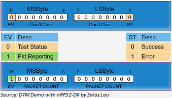
Upon receiving a command, the firmware returns the status of a command to the sender. In case of TEST END command, the total number of packets received is returned to the sender. The picture above shows the format of the two types of event supported.
The message flow
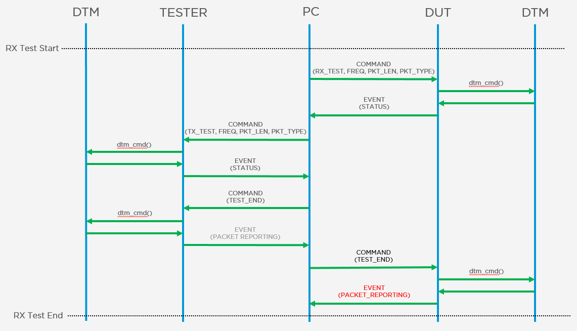
The picture above shows the RX test message flow from PC to the TESTER and Device Under Test (DUT). The PC starts the test by setting up the DUT in receiving mode and the TESTER to transmit packets. The test parameters, including the frequency, packet length and packet type, must be matched between the TESTER and DUT. Otherwise, the test fails. At the end of the test, TEST_END is sent to the TESTER to stop the transmission and then to the DUT to stop reception. The DUT responds with the total number of packets received.
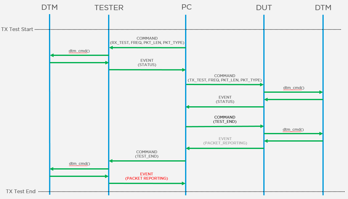
The picture above shows the TX test message flow from PC to the TESTER and Device Under Test (DUT). The PC starts the test by setting up the TESTER in receiving mode the DUT to transmit packets. The test parameters, including the frequency, packet length and packet type, must be matched between the TESTER and DUT. Otherwise, the test fails. At the end of the test, TEST_END is sent to the DUT to stop the transmission and then to the TESTER to end the reception. The TESTER responds with the total number of packets received.
As the duration of transmission and packet parameters are all known, the number of packets transmitted can be deduced. By checking against the packets received, PER can be worked out to determine whether the DUT passed or failed the test. The same flow of RX and/or TX tests can be repeated for different frequencies and packet sizes.
Production Screening based on DTM
The setup
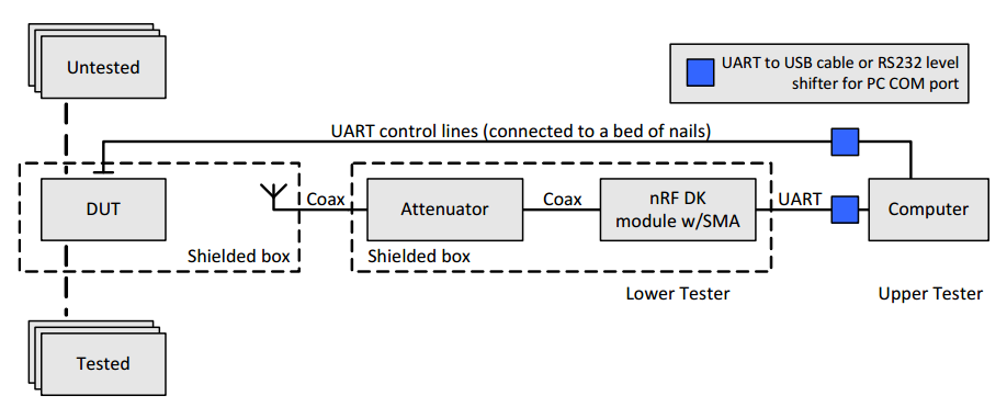
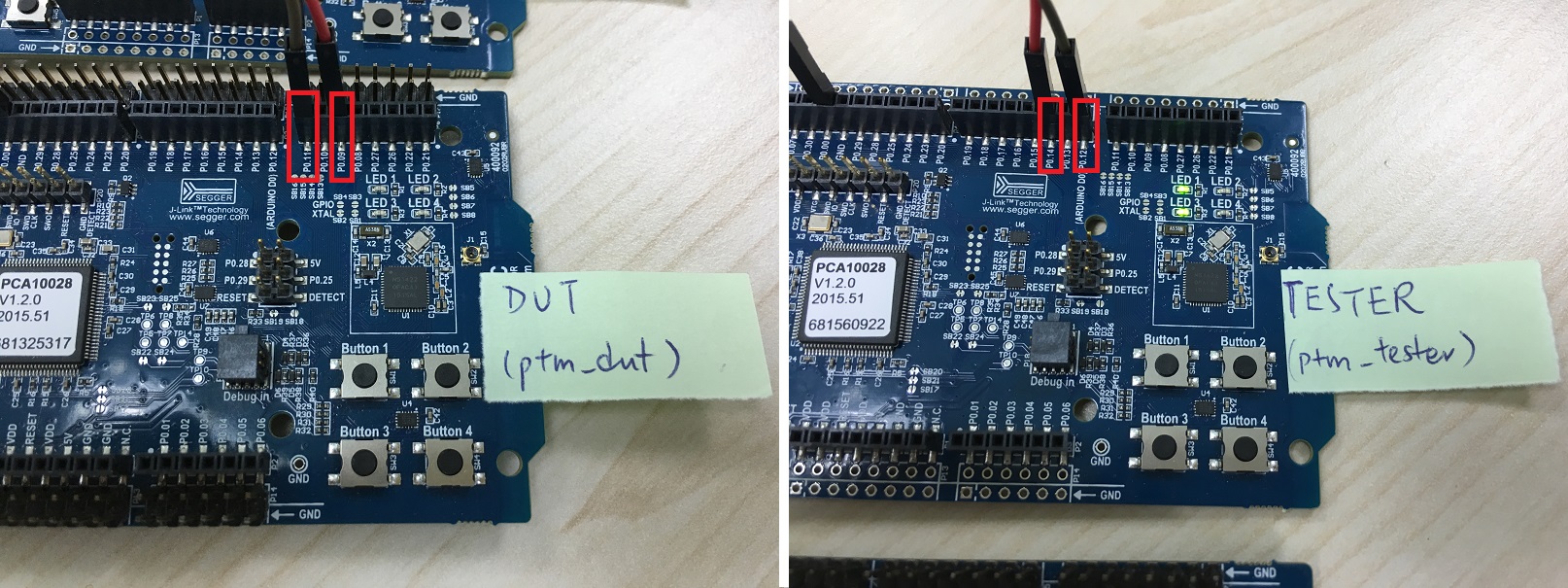
The picture above shows a production screening setup derived from the DTM setup as shown in the previous section. The major differences are:
-
The PC is out of the picture. The TESTER and DUT are connected directly through UART. The TESTER becomes the driver of the test and the DUT receives commands from the TESTER to carry out requested actions
-
The TESTER and DUT are put in the same shielded box. As the whole setup is shielded from the ambient RF noise, it is not necessary to connect the TESTER and DUT with a coaxial cable and attenuators
As the whole setup is contained in a single shielded box, it is relatively simple to come up with a portable station. The setup can also be duplicated in a relatively low cost. Such a portable low cost screening station facilitates the scaling up of production throughput.
The TESTER is running a new application which drives the whole screening process by sending commands to remote DTM on DUT and the local DTM. The DUT is running a 'slightly' modified DTM firmware to act as the passive party.
Extension to the DTM vendor specific commands
To simplify computation of PER, a new vendor specific command is added to set the number of packets to be transmitted for each run of the TX test. In the original DTM, the TESTER/DUT transmits packets indefinitely until TEST_END is received. This relies on the TESTER to keep the time the test has run to deduce the number of packets transmitted. While this is relatively trivial on PC, it would be a hassle on an SoC. To avoid such time keeping, a new vendor specific command is added for setting the number of packets to be sent per TX test. After the number of packet is set, the TESTER/DUT stops transmitting packets upon the set number of packet is sent even if TEST_END is not received. In such a manner, it would be relatively trivial to divide the number of packets received by that of transmitted to come up with the PER.
The message flow
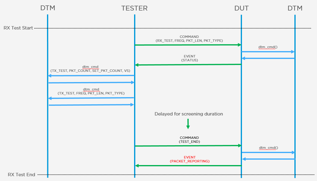
Without the PC, the TESTER is sending command frames to the DUT through UART directly. At the beginning of the test, the TESTER puts the DUT in receiving mode. Then the TESTER set itself up to transmit the desired number of packets and start the transmission locally. The TESTER waits at least the minimum time needed to send the desired number of packets. This can be computed by dividing the total number of bytes (packet length multiplied by packet count) to be sent. After the delay, the TESTER should send TEST_END command to DUT to obtain the received packet count in the response from the DUT.
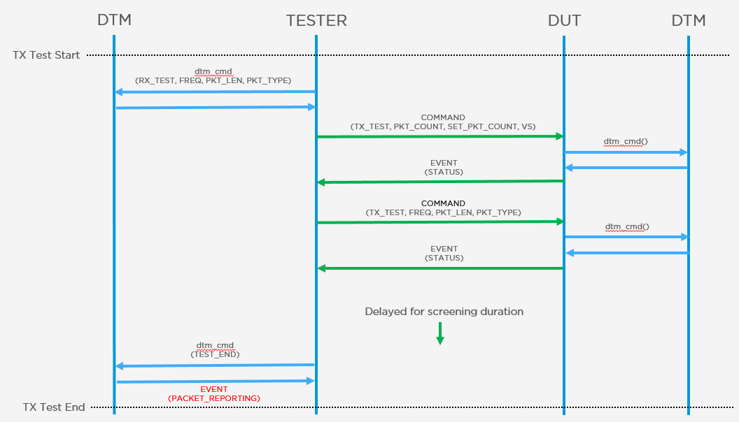
The TX test is an exact reverse of the RX test. The TESTER puts itself in receiving mode. After that, the TESTER sets the desired number of packets to be transmitted by the DUT and starts the TX test by sending commands to the DUT through UART. The TESTER waits at least the minimum time needed to receive the desired number of packets. After the delay, the TESTER should send TEST_END command locally to obtain the received packet count in the response from the TESTER.
PER can then be computed with the number of packet transmitted and received to determine whether the DUT passed or failed the screening.
The Demo
Hardware
Two nRF51-DK(PCA10028) or nRF52-DK(PCA10040)
Firmware
- Download and extract nRF5 SDK v12.1.0
- Download and extract ptm_20161206.zip to $(SDK_FOLDER)/examples
- Choose either project in pca10028 or pca10040 according to your hardware, compile and program to run
- Note: No SoftDevice is required to run this screening
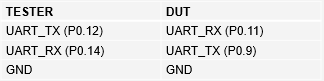
Connections
LED indicators
LED1(P0.21) - TX test passed
LED2(P0.22) - TX test failed
LED3(P0.23) - RX test passed
LED4(P0.24) - RX test failed
- The demo was tested extensively on PCA10028 which is the nRF51 DK, and briefly on PCA10040
- The demo was tested on SDK v12.1.0 . It should work with older versions of SDKs as DTM was not changed much as SDK evolves
- The role of TESTER and DUT can be inter-changed for other system considerations such as in-station programming of the unit. There is no restriction on the devices being screened to be in the TESTER or DUT role, it is all up to the final screening station design
- The demo was running on DKs for convenience on getting the materials. However, it is not recommended that DKs be used in a production setting. The DKs are manufactured to a quality which is sufficient for development but it is not mean for heavy duty usage as a production tool. It is recommended that PCBs which are manufactured to a high quality standard be fitted into the production screening stations
Further down the road
-
The current setup is completely standalone with no attachment to any programming facility. It is foreseeably desirable that some programming capability be included in the screening station so that the programming of the screening firmware, or even the production firmware, can be integral steps of the screening. This should be achievable with MCU that is capable of running CMSIS-DAP. With such programming capability, the station can be a one-stop-shop which screening firmware, and production firmware, can be programmed before, and after, the screening.
-
The current setup is able to distinguish units which is operational and capable of transmitting and receiving data. However, it is unable to screen according to a certain threshold of sensitivity. RSSI measurement results for RX test can in fact be included to extend the screening.
-
The test result indication is of a demonstration level and very minimal, richer representation of results can be implemented for ease of use on production line.
References
Bluetooth Core Specifications v 4.1 vol. 6 part F - Direct Test Mode by Bluetooth SIG
Direct Test Mode in nRF5 SDK on Nordic InfoCenter
nAN34 - Setting up production test using DTM on Nordic InfoCenter
Salas Lau, "DTM Demo with nRF52-DK"
