Setup
- nRF54L15 custom board, nPM1300 PMIC on I2C at 0x6B
- nRF Connect SDK v2.9.2, board target
nrf54l15dk/nrf54l15/cpuapp - Battery: 1000 mAh 3.7 V single-cell LiPo, two-wire pack (no thermistor)
- USB-C input on the board's own connector
Symptom
The battery does not charge. Left connected to USB-C for six hours with no change in voltage or reported percentage (stuck at 4%).
BCHGCHARGESTATUS reads 0x00 throughout - bit 0 (BATTERYDETECTED) never asserts, so no charging phase is ever entered. BCHGERRREASON reads 0x00, so no error is being flagged either.
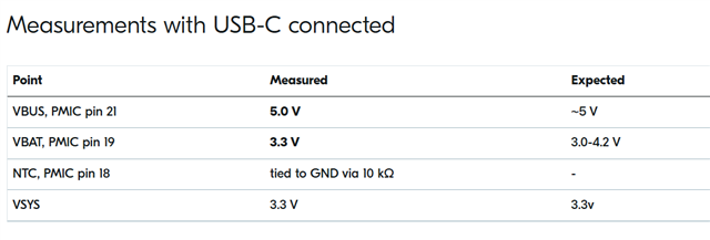
Measurements with USB-C connected
| Point | Measured | Expected |
|---|---|---|
| VBUS, PMIC pin 21 | 5.0 V | ~5 V |
| VBAT, PMIC pin 19 | 3.3 V | 3.0-4.2 V |
| NTC, PMIC pin 18 | tied to GND via 10 kΩ | - |
| VSYS | 3.3 V | 3.3v |
So the input is present, the cell is present, and a thermistor substitute is fitted. The PMIC still reports no battery detected.
Firmware readings over I2C
Battery: 4%  29.2 C (die)  3710 mV  22 mA  chg 0x00
charger status 0x00
charger error  0x00
Temperature is read from SENSOR_CHAN_DIE_TEMP, because SENSOR_CHAN_GAUGE_TEMP returns a value outside the valid range (approximately -88 C) and the firmware falls back. This was true both before and after fitting the 10 kΩ at the NTC pin - the NTC channel still reads out of range.BATTERYDETECTED (bit 0) is inconsistent across boards and does not correlate with whether a 10 kΩ NTC substitute is fitted. One board with no NTC resistor reports 0x01 at 3666 mV; another with the resistor fitted reports a fully charged cell. A third reported 0x00 at 3710 mV.
Devicetree
npm1300_charger: charger {
    compatible = "nordic,npm1300-charger";
    term-microvolt = <4200000>;
    term-warm-microvolt = <4100000>;
    current-microamp = <500000>;
    dischg-limit-microamp = <1000000>;
    vbus-limit-microamp = <500000>;
    thermistor-ohms = <10000>;
    thermistor-beta = <3380>;
    charging-enable;
};
Question
1. Why does BATTERYDETECTED stay clear with 3.3 V on VBAT? What conditions must be met for the nPM1300 to assert it? Does battery detection require the charger to be actively running, or should it assert whenever a cell is present?
2. What is the correct configuration for a two-wire pack with no thermistor? Is a fixed 10 kΩ from the NTC pin to GND the right substitute, and should thermistor-ohms/thermistor-beta remain as above when doing that? Is there a way to disable NTC monitoring entirely so it cannot block charging?
3. Why does SENSOR_CHAN_GAUGE_TEMP still read out of range after fitting the resistor? Should a fixed 10 kΩ produce a valid ~25 C reading on that channel?
4. Reading charge current direction. SENSOR_CHAN_GAUGE_AVG_CURRENT appears to return magnitude only - every reading in every log has been positive, including while the battery was visibly discharging. Is the sign available, and if not, what is the recommended way to distinguish charging from discharging besides BCHGCHARGESTATUS?
5. Reading back LED state. The three LEDs (LEDDRV0-2 in host mode) are driven successfully via the Zephyr LED API. Is there a way to read back their current on/off state from the PMIC, or must the application track it?
Available on request
Full schematic, app.overlay, prj.conf, and raw register dumps.
What I am trying to achieve
Reliable battery percentage, battery temperature, and a correct charging/discharging indication, plus readable LED state - all over I2C from the nRF54L15.We also do not deep the voltage output of 1.8v So we are using the VSET2 for 3.3v