LFXO doesn't start with nRF54LM20B and nPM1300 until a debugger reset or RTT session is started

Hello,

we have a custom PCB with the NRF54LM20B (nRF54LM20B_xxAA_ENGB) and nPM1300, and we are observing odd behavior with the LFXO failing to start from a cold boot, causing the system to hang in MCUBoot (which waits for the LFXO to be ready to supply the GRTC), unless an RTT session is attached or the board reset via the debugger, which causes the LFXO to start successfully. The LFXO also starts successfully from warm (re)-boots.

The mounted LFXO crystal is the ECS-.327-7-12-C-TR with a load capacitance of 7pF and ESR of 90k: https://ecsxtal.com/products/crystals/surface-mount-crystals/ecs-327-7-12-c-tr/

The device tree is configured as follows:

/* ECS-.327-7-12-C-TR (CL = 7 pF): C_INT ~= 2 * CL - ~1 pF stray (internal-cap equation). */
&lfxo {
load-capacitors = "internal";
load-capacitance-femtofarad = <13000>;
};

/* ECS-320-8-37B (CL = 8 pF): C_INT ~= 2 * 8 pF - ~1 pF stray, as for &lfxo. */
&hfxo {
load-capacitors = "internal";
load-capacitance-femtofarad = <15000>;
};

The system is powered by an nPM1300, which provides the 1V8 VDD of the nRF via BUCK1. The BUCK1 is configured to 1V8 via the VSET resistor (47k).
The schematic for the nPM1300 has been reviewed by Nordic before, and all capacitances (i.e. input and output capacitors) match the requirements. I don't think the PMIC is the issue.

The debugger is an nRF54LM20DK, connected with the 10-pin cable to our PCB. The board programs fine.

We also have a RESET button wired to the reset of the MCU, but that doesn't seem to have any effect (it does restart the board, but LFXO still fails to start). The reset has to come from the debugger, either via the reset command (below), or attaching an RTT session. Something else must happen during the debugger reset.

[15:08:47] nrfutil-device reset --serial-number 001051895398 --json
[15:08:48] Success.

Below is a screenshot of the power before and after the debugger reset (with the reset in the middle).
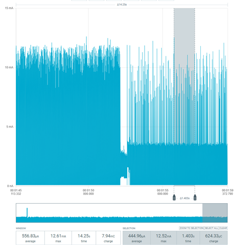
I have tried the following things without much success:

  • Changing the internal load capacitors values (from 9000 to 15000) -> no change in behavior
  • Probing the 1V8 rail powering the MCU -> nothing unusual, the 1V8 becomes stable within 200uS of VBAT/VBUSIN without any peaking, dips, brown-out or noise
  • Probing the LFXO -> when the LFXO doesn't start, I just see two weak pulses on the crystal and back to nothing. when it is running, I see a sine-wave of around 32.768kHz.

Are there any registers I can probe or read-out that tell me what could be going wrong and why the LFXO is not starting?
Is the crystal maybe out-of-spec for the nRF54LM20B?
Is this maybe an issue with the ENGB SoC itself or part of an errata?

We are using the nRF Connect SDK v3.4.1 and the board config uses MCUboot with the second app slot on an external flash IC, very similar to the nRF54LM20DK configuration.

Thank you!

Parents
  • Hello Einar,

    as far as I understand, this is a different issue. The other post from amo-inv was about the ordering, for which the fix you linked to is already included in the v3.4.1 SDK we're using.

  • Hi,

    You are right, this is a different matter. I am not able to say what caues this, though. A few questions:

    1. Does this happen consistently, or only some times?

    2. How did you verify that the booltoader wait for the LFXO to start? Can you share that details (where it is waits etc)?

    3. Have you verified that this only happens when using LFXO? What if you configure LFRC in both the application and bootloader, does it stil happen? You can do that by adding CONFIG_CLOCK_CONTROL_NRF_K32SRC_RC=y in the configuration for both, and additionally CONFIG_CLOCK_CONTROL_NRF_K32SRC_RC_CALIBRATION=n in the bootlaoder config.

  • Hello Einar,

    1. This happens on every cold boot. We can also see a slightly higher current consumption in this state (roughly 100uA).

    For Question 2 and 3 I have used the Nordic MCP to dig deeper into the callstack and asked it for a write-up, please see below:


    1. It happens consistently on every power-on reset. It never happens after a warm reset, after a debugger reset, or once an RTT session is open.

    2. Located by attaching GDB without a reset to a hung board and reading the call stack and registers before resuming.

    With the default config (CONFIG_NRF_GRTC_TIMER_SOURCE_LFXO=y, GRTC CLKSEL=LFXO), it spins in the SYSCOUNTER ready loop (SYSCOUNTERH.BUSY):

      nrf_grtc_sys_counter_low_get                  nrfx/hal/nrf_grtc.h:1742
      __nrfy_internal_grtc_sys_counter_ready_check  nrfx/haly/nrfy_grtc.h:1051
      nrfy_grtc_sys_counter_start                   nrfx/haly/nrfy_grtc.h:304
      nrfx_grtc_syscounter_start                    nrfx/drivers/src/nrfx_grtc.c:529
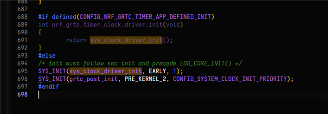
      sys_clock_driver_init                         zephyr/drivers/timer/nrf_grtc_timer.c:557 (SYS_INIT EARLY, 1)

    With CONFIG_NRF_GRTC_TIMER_SOURCE_SYSTEM_LFCLK=y, the LFXO is started via CLOCK.TASKS_LFCLKSTART (LFCLK.SRC=LFXO) and EVENTS_LFCLKSTARTED never arrives.

    Register state:
      RESET.RESETREAS        = 0x0
      XOSC32KI.INTCAP        = 0xA (DTS value, written at EARLY 0, before the GRTC starts)
      XOSC32KI.STATUS        = 0x7 after attach
      CLOCK.LFCLK.STAT       = 0x10001 after attach

    The firmware is still in the wait loop 8-15 s after power-on. The LFXO starts as soon as the debugger connects, and the boot then continues without a reset.

    3. It also happens with LFRC. Configuration: CONFIG_CLOCK_CONTROL_NRF_K32SRC_RC=y in both images, plus CONFIG_CLOCK_CONTROL_NRF_K32SRC_RC_CALIBRATION=n in MCUboot. The GRTC then runs on LFLPRC, and LFCLK.STAT = 0x10000 (LFRC running).

    Clock init then passes, but MCUboot hangs during image validation, in the __WFE() loop waiting for the CRACEN interrupt:

      nrf_security_event_wait       nrf/subsys/nrf_security/src/utils/nrf_security_events.c:54
      cracen_wait_for_cm_interrupt  .../cracen/sxsymcrypt/src/platform/baremetal/interrupts.c:108
      sx_hash_wait                  .../cracen/sxsymcrypt/src/hash.c:257
      cracen_hash_update            .../cracen/cracenpsa/src/cracen_psa_hash.c:147
      bootutil_img_hash             bootloader/mcuboot/boot/bootutil/src/bootutil_img_hash.c:188
      bootutil_img_validate         bootloader/mcuboot/boot/bootutil/src/image_validate.c:354

    On debugger attach (no reset), the core is in cracen_direct_isr_handler, and after resuming it boots the application.

    Also tested, with no effect:
    - VREGMAIN in LDO instead of DC/DC
    - POWER.TASKS_CONSTLAT at boot (CONSTLATSTAT = 1 confirmed)
    - Skipping the erratum 37 workaround (FICR 0x33/0x01, NRF_TAD + 0x40C)

    So the hang is not LFXO-specific. After a power-on reset, neither the LFXO start nor the CRACEN completion interrupt happens until a debug connection is made. What does debug power-up enable on the nRF54LM20B (EngB) that firmware does not?

Reply
  • Hello Einar,

    1. This happens on every cold boot. We can also see a slightly higher current consumption in this state (roughly 100uA).

    For Question 2 and 3 I have used the Nordic MCP to dig deeper into the callstack and asked it for a write-up, please see below:


    1. It happens consistently on every power-on reset. It never happens after a warm reset, after a debugger reset, or once an RTT session is open.

    2. Located by attaching GDB without a reset to a hung board and reading the call stack and registers before resuming.

    With the default config (CONFIG_NRF_GRTC_TIMER_SOURCE_LFXO=y, GRTC CLKSEL=LFXO), it spins in the SYSCOUNTER ready loop (SYSCOUNTERH.BUSY):

      nrf_grtc_sys_counter_low_get                  nrfx/hal/nrf_grtc.h:1742
      __nrfy_internal_grtc_sys_counter_ready_check  nrfx/haly/nrfy_grtc.h:1051
      nrfy_grtc_sys_counter_start                   nrfx/haly/nrfy_grtc.h:304
      nrfx_grtc_syscounter_start                    nrfx/drivers/src/nrfx_grtc.c:529
      sys_clock_driver_init                         zephyr/drivers/timer/nrf_grtc_timer.c:557 (SYS_INIT EARLY, 1)

    With CONFIG_NRF_GRTC_TIMER_SOURCE_SYSTEM_LFCLK=y, the LFXO is started via CLOCK.TASKS_LFCLKSTART (LFCLK.SRC=LFXO) and EVENTS_LFCLKSTARTED never arrives.

    Register state:
      RESET.RESETREAS        = 0x0
      XOSC32KI.INTCAP        = 0xA (DTS value, written at EARLY 0, before the GRTC starts)
      XOSC32KI.STATUS        = 0x7 after attach
      CLOCK.LFCLK.STAT       = 0x10001 after attach

    The firmware is still in the wait loop 8-15 s after power-on. The LFXO starts as soon as the debugger connects, and the boot then continues without a reset.

    3. It also happens with LFRC. Configuration: CONFIG_CLOCK_CONTROL_NRF_K32SRC_RC=y in both images, plus CONFIG_CLOCK_CONTROL_NRF_K32SRC_RC_CALIBRATION=n in MCUboot. The GRTC then runs on LFLPRC, and LFCLK.STAT = 0x10000 (LFRC running).

    Clock init then passes, but MCUboot hangs during image validation, in the __WFE() loop waiting for the CRACEN interrupt:

      nrf_security_event_wait       nrf/subsys/nrf_security/src/utils/nrf_security_events.c:54
      cracen_wait_for_cm_interrupt  .../cracen/sxsymcrypt/src/platform/baremetal/interrupts.c:108
      sx_hash_wait                  .../cracen/sxsymcrypt/src/hash.c:257
      cracen_hash_update            .../cracen/cracenpsa/src/cracen_psa_hash.c:147
      bootutil_img_hash             bootloader/mcuboot/boot/bootutil/src/bootutil_img_hash.c:188
      bootutil_img_validate         bootloader/mcuboot/boot/bootutil/src/image_validate.c:354

    On debugger attach (no reset), the core is in cracen_direct_isr_handler, and after resuming it boots the application.

    Also tested, with no effect:
    - VREGMAIN in LDO instead of DC/DC
    - POWER.TASKS_CONSTLAT at boot (CONSTLATSTAT = 1 confirmed)
    - Skipping the erratum 37 workaround (FICR 0x33/0x01, NRF_TAD + 0x40C)

    So the hang is not LFXO-specific. After a power-on reset, neither the LFXO start nor the CRACEN completion interrupt happens until a debug connection is made. What does debug power-up enable on the nRF54LM20B (EngB) that firmware does not?

Children
  • Hi,

    When a debugger is attached that takes the device out of low power mode, essentially forcing on regulators and HF clock (not crytal) and quite a few other internals in the SoC. I am suspisious there is a supply issue, either on the nRF54LM20 side (particularily aroudn the decoupling capacitors), or potentially around the nPM1300. Has the whole board been reviewed by Nordic? Can you share the link or case number for that?

    And to try to narrow this down a bit more experimentally:

    1. Can you supply via a lab supply, buypassing the nPM1300 and see if that makes a difference?

    2. Does it matter if the debugger is disconnected physically or not, or just wether it is attached (so the nRF enters debug mode)? I am wondering if the nRF could be back powered via the debugger and that perhaps causes some additional confusion and would like to rule that out.

    3. Do you have multiple boards and if so can you test another board and see if it behaves the same way?

    4. If either other boards also behave the same or you do no thave others, can you double check soldering and connections for all the decoupling capacitors?

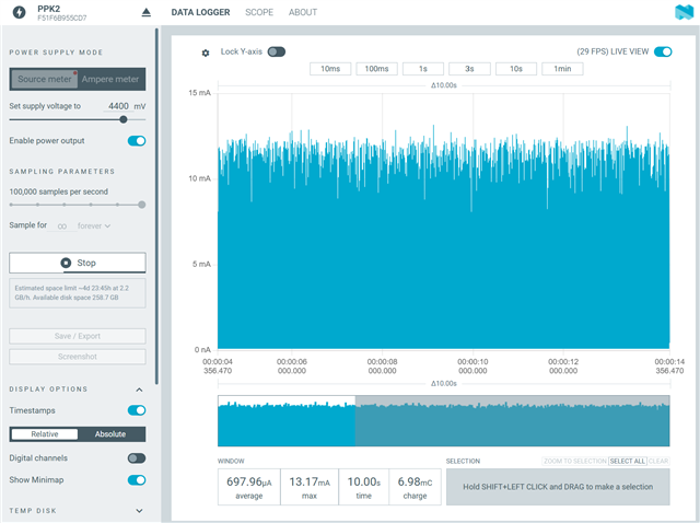
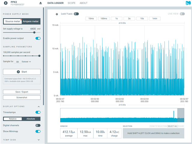
    5. You write that you see 100uA additional current consumption in the bad state. What aboslute number do you measure? (If the absolute sonsumptoin is on that order, the number is too low for for instance CPU running and also for most other typical problems, so I am having problems reading much out of it).

  • Hello Einar,

    thank you for your reply. Yes, the schematic for the SoC and PMIC has been reviewed by Nordic, and is more or less a copy/paste of the reference design, please see Case ID: 35487, which also contains the full schematic for your reference.

    Let me answer your questions:

    1. I have tried this, unfortunately no difference. I'm powering the 1V8 rail directly via the PPK2, same behavior, the board only boots into application after a debugger reset.

    2. Just having the debugger physically attached doesn't help. It needs that active debugger reset.

    3. Yes this happens across multiple boards.

    4. Decoupling caps look fine to me.

    5. Please see the following two screenshots that show the power consumption of the whole system on VBAT (going into the nPM1300) in the stuck state (first) and after a debugger reset (second). Note that this is the whole system power (including sensor ICS), which is why it is rather high.

    Hung state:

    After a debugger reset:

  • Hi,

    I see (I did not see anything standin out in the review case, 354877). I have been attempting to try to reproduce something similar on a DK without success.

    It is a bit odd that the issue you see when debugging seemingly "moves around", and I am having problems seeing HW issues. Is it possible to run your fimrware on the nRF54LM20 DK? If do do, do you reproduce the issue there?

    Other than that, can you say a bit about your firmware, and if you have made any significant changes to SDK libraries or MCUboot? Or is there other information you have that could be relevant?

  • Hello Einar,

    Yes we also have the nRFLM20DK as a board target and we have both the 0.7.0 and 0.3.4 nRF54LM20DK here, and I have some interesting news to share. I am powering the board via the PPK2.

    - I'm not able to reproduce the issue on the 0.7.0 DK (which has the rev 1 silicon)

    - I am able to reproduce the issue on the 0.3.4 DK IF, and only IF, the embedded board debugger is powered during the first cold boot.

    - Our board does indeed boot fine every time if the attached debugger is off or disconnected.

    So something in the embedded debugger seems to be interfering in the cold boot, and the ENGB/ENGA SoC seems to be affected by this, while the Rev1 silicon is not.

    I'm going to run some more tests to make sure this is 100% the case, but at least we have an answer and reliable workaround for now. 

Related