nRF52840 dongle sometimes goes to the DFU mode at power-on

Hi,

I have two nRF52840 dongles. Both configured to use external power source (SB2 cut, SB1 soldered).

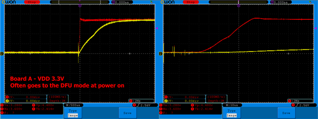
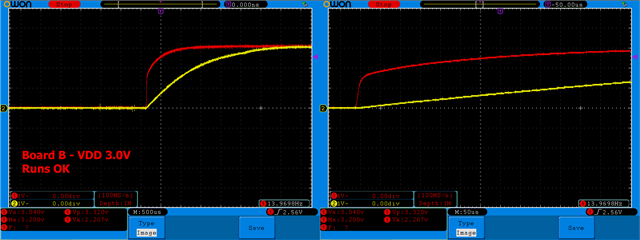
The first one goes always to my nRF program on power on (battery connected). The second one often goes to the DFU mode on power-on (red LED pulsating). I would like the system to go to the program directly all the time.

Note: I saw a a 2 years old thread in Q&A that is basically same as mine. I followed hints from there but same situation here, no pins are used that are connected to the reset pin or DFU mode.

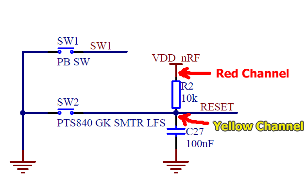
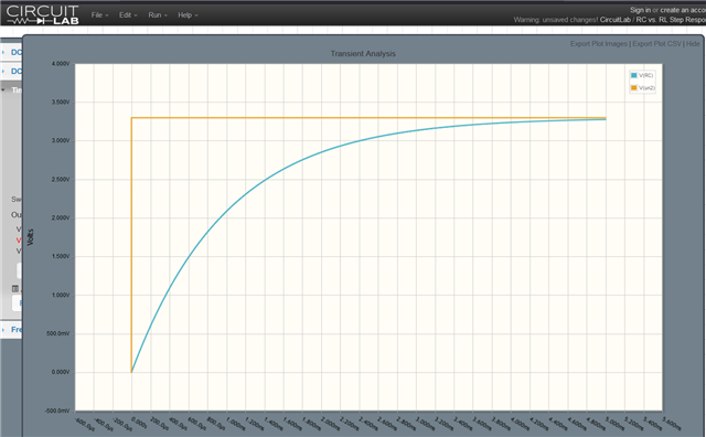
I do not see major difference between the boards except the VDD rail. Is there a recommendation how fast/slow should VDD rise? For the nRF52840 chip or directly for the dongle as it has resistor and capacitor on the SW2 DFU button connected to the RESET pin. Maybe the timing of the VDD rise is important here.

The working board uses TC1015 3.0V regulator with a small bypass capacitor (should have fast rise time) on the LDO BP pin. The PicoOLED board uses RT9193 3.3V regulator with 22nF bypass capacitor (should have slower rise time).

If needed I can probe the VDD and RESET lines with oscilloscope.

Thanks,
Rado

Parents
  • Hi Rado,

    The rise time of VDD must  not be too slow, if not there may not be a power-on-reset. This is documented under POWER. I do not immediately see how this should be related to the device staying in DFU mode, though.

    I am not sure which HW you are using, as you are referring to some regulators and caps, but at the same time you are referring to solder bridges on the dongle. Assuming these are our dongles, which versions are they? Also, are you using the stock bootloader, or have you flashed your own bootloader?

    If the board has the open bootloader it will enter reset mode after a pin reset. If there is no pin reset, the bootloader will always start the application provided a valid application is present. So I would first of all double check that there is nothing on the HW that causes the reset pin to be asserted for some reason. scoping the RESET pin as you suggest would be very sensible. (Scoping VDD also would not hurt)

  • Hi Einar,

    sorry for the above confusing description.

    Yes, the dongles are two Nordic nRF52840 dongles. Nothing from the other HW connected to the dongles is important, we can consider it just as an external VDD power source for the dongles.
    Both the dongles have stock bootloader. Not sure how to find the dongles version. I can see following codes on PCB: 400250, 0379RUBR.

    I am attaching screenshots from oscilloscope.
    Measurement was done in two channels. Connected to both ends of the R2 resistor. (Red: VDD nRF, Yellow: Reset line).

    The problematic configuration that has 3.3V LDO rises fast. 55 us to full 3.3V. I was expecting slower rise time here.
    The OK configuration that has 3.0V LDO rises fast in first half (50 us) but it takes 1 ms to the full 3.0V.
    Still should be ok. The max VDD rise time in the documentation is much higher.

    Can the slow voltage rise on the RESET line (caused by C27 and R2 on the nRF52840 dongle) be the problem?
    Is it possible that the nRF chip power-on logic switches the chip to an active state while the reset voltage is still under a threshold?

    Does the nRF52840 SOC have a register for a startup delay definition?

    Thanks for help.
    Rado

  • Hi,

    The VDD rise time is not the issue here. However, the reset pin seems to be held low for so long that this will be a pin reset, and when the RESETREAS indicate a pin reset, the bootloader will enter DFU mode instead of starting the application.

    I have not seen any other reports of this being an issue with the dongle though, so I wonder if you did any modifications that can have affected this? If not, can you check the versions? That is printed on the white sticker on the back-side, on the second line (below "PCA10059").

Reply
  • Hi,

    The VDD rise time is not the issue here. However, the reset pin seems to be held low for so long that this will be a pin reset, and when the RESETREAS indicate a pin reset, the bootloader will enter DFU mode instead of starting the application.

    I have not seen any other reports of this being an issue with the dongle though, so I wonder if you did any modifications that can have affected this? If not, can you check the versions? That is printed on the white sticker on the back-side, on the second line (below "PCA10059").

Children
  • Hi,

    no modification of the dongle except the SW1/SW2 points configuration for external VDD. According documentation.

    The version on the sticker is
    2.1.1
    2022.17
    F5:22:E5
    95:A0:31

    The RC element on the reset line behaves as designed according the resistor and capacitor values.
    I quickly checked in an online simulator. It rises few milliseconds.

    Maybe the working configuration for my second board was saved by much larger output filtering capacitor on the LDO output. It is 10uF vs 1uF on the problematic configuration (still within LDO manufacturer recommendation).
    The working one has slower VDD rise thanks to this and probably the nRF is longer in hold by the power-on logic. Giving more time to the reset line to be in high state.

    I would try to replace the dongle reset capacitor to a smaller value but it is physically too small for me to try :-) I will rather try to increase the filtering capacitor on VDD line to 10uF.
    To see if it helps.

    Rado

  • Hi Rado,

    That is sound reasoning. You need to do something externally to handel this, as there is no configurable startup delay.

  • Just a quick update. I added 10uF capacitor to the VDD rail. As addition to the original 1uF. It helped but not 100% time. Still sometimes it powers on to the DFU mode.

Related