
Nordic's Power Profiler Kit (PPK) is an inexpensive piece of hardware that can provide a significant amount of insight into the operation and performance of your project. Although there is a lot that you can learn by experimenting with the PPK using the Power Profiler app that's available inside nRF Connect for Desktop, the PPK can also be integrated deeper into your workflow to provide insight into how your design is performing as the hardware/software matures.
Regardless of whether or not you've used the PPK before it's a good idea to take a few minutes to check out the excellent "getting started" video here to remind yourself of its operation and nomenclature.
Connecting the PPK
The communication between the PC and the PPK uses Segger's Real-Time Transfer (RTT) functionality. This is essentially a very fast socket that is created by the J-Link debug probe that moves data between the J-Link drivers on a PC and a some RAM buffers on the microcontroller. The PPK itself doesn't have an onboard J-Link like Nordic development kits do so the typical scenario is to have the PPK simply hijack the Device Under Test's (DUT's) debug probe on a development kit. A standalone J-Link or an ancillary development kit can also be used to talk to the PPK if the DUT needs to use its own debug probe for programming or debugging. The various scenarios are described in the PPK's documention.
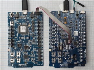
This blog post assumes that you have access to two development kits and it uses the measuring current on an nRF5 DK while debugging configuration. In short, this look like:
- An unmodified development kit plus a 10-pin, IDC cable is acting as the PPK's J-Link.
- The IDC cable runs from the unmodified development kit's "Debug out" header to the PPK's "Debug in" header.
- The development kit to use as the DUT has been modified so its "SB9" solder bridge is no longer shorted.
- The PPK itself is plugged into the DUT developement kit and the PPK's "DUT select" switch is set to "DK", the "Power select" switch is set to "DK", and the "COM" switch is set to "EXT".
After both development kits are plugged in to the PC and powered on it's a good idea to use nrfjprog to read their serial numbers:
$ nrfjprog -i
682294737
682802368
Make note of which serial number corresponds to the DUT and which one is the PPK. To simplify, these will be referred as DUT_SN and PPK_SN moving forward. Now it's possible to reprogram the DUT without touching the PPK:
$ nrfjprog -s DUT_SN --program SOME_FW.hex --sectorerase -r
The PPK_SN will be used in a similar manner when talking to the PPK from the command line.
Talking to the PPK
The stream of data that is exchanged with the PPK is split into packets using serial control characters. Commands that are sent to the PPK consist of a one-byte OPCODE followed by zero or more parameters. Data that is streamed from the PPK back to the PC is preceded by a 32-bit timer value for use as a timestamp. Interfacing with the PPK from the command line is simply a matter of building a library that can encode and decode these packets.
The PPK's firmware is not open source but the source code for the PPK plugin for nRF Connect is available on github. The code from this plugin provided guidance when grooming an unofficial project created by an engineer in Nordic R&D to create an updated ppk_api project. The ppk_api is written in Python 3 and requires the 32-bit Python build to be compatible with J-Link drivers.
The first step to install it is to ensure that 32-bit Python 3 is installed:
$ python
Python 3.7.4 (tags/v3.7.4:e09359112e, Jul  8 2019, 19:29:22) [MSC v.1916 32 bit (Intel)] on win32
Type "help", "copyright", "credits" or "license" for more information.
>>>
Then clone or download the ppk_api, open a command shell inside the newly-created "ppk_api" directory, and use pip to install the required modules:
$ pip3 install --user -r requirements.txt
If everything worked then a help message can be printed:
$ python main.py -h
usage: main.py [-h] [-s SERIAL_NUMBER] [-a AVERAGE]
               [-w [TRIGGER_MICROSECONDS]] [-n [TRIGGER_COUNT]]
               [-e EXTERNAL_VDD] [-c] [-p [POWER_CYCLE_DUT]] [-o OUT_FILE]
               [-z] [-g] [-t TRIGGER_MICROAMPS | -x] [-k | -f] [-v | -j]

optional arguments:
  -h, --help            show this help message and exit
  -s SERIAL_NUMBER, --serial_number SERIAL_NUMBER
                        serial number of J-Link
  -a AVERAGE, --average AVERAGE
                        print average current over time
  -w [TRIGGER_MICROSECONDS], --trigger_microseconds [TRIGGER_MICROSECONDS]
                        set trigger window in microseconds [1000, 52000]
  -n [TRIGGER_COUNT], --trigger_count [TRIGGER_COUNT]
                        set number of trigger buffers to capture
  -e EXTERNAL_VDD, --external_vdd EXTERNAL_VDD
                        set external regulator voltage [2100, 3600]
  -c, --clear_user_resistors
                        clear user calibration resistors
  -p [POWER_CYCLE_DUT], --power_cycle_dut [POWER_CYCLE_DUT]
                        power cycle the DUT and delay
  -o OUT_FILE, --out_file OUT_FILE
                        write measurement data to file
  -z, --png             create .png graph(s) of data in out_file
  -g, --spike_filtering
                        enable spike filtering
  -t TRIGGER_MICROAMPS, --trigger_microamps TRIGGER_MICROAMPS
                        set trigger threshold in microamps
  -x, --enable_ext_trigger
                        enable 'TRIG IN' external trigger
  -k, --skip_verify     save time by not verifying the PPK firmware
  -f, --force           program the PPK firmware if necessary
  -v, --verbose         print logging information
  -j, --json            print output as parsable JSON
Where we're going, we don't need GUIs
A simple example can illustrate how a command line interface to the PPK is useful. Attached to this blog are three firmware hex files, each built from the "ble_app_beacon" example in SDK15.3. Specifically, they are built to run on a PCA10040 development kit and have the following implementation details:
- "0_vanilla_ble_app_beacon.hex" is the unmodified example, built for the release configuration.
- "1_dcdc_enabled_ble_app_beacon.hex" is the same example with the addition of a single line: "sd_power_dcdc_mode_set(NRF_POWER_DCDC_ENABLE);"" was added to line 300 of "main.c".
- "2_increase_adv_int_dcdc_enabled_ble_app_beacon.hex" has the DCDC converter enabled plus the advertising interval has been increased from 100ms to 1000ms.
Download the three hex files and copy them into a directory called "data" inside the "ppk_api" directory. Then create a blank file in the "ppk_api" directory called "example.bat" and open it in a text editor. This will be a simple script that loops through the names of any hex files in the "data" directory and takes care of programming the DUT and using the PPK to measure the average current over a two second interval.
@echo off
set DUT_SN=682454138
set PPK_SN=682294737
for /r %%i in (data\*.hex) do (
	echo Programming: %%i
	nrfjprog -s %DUT_SN% --program %%i --sectorerase -r --quiet
	python main.py -s %PPK_SN% -a 2 -p 1 -o %%i -z -f
)
Make sure to replace the DUT_SN and PPK_SN serial numbers according to the instructions above. Running the batch file results in something like this:
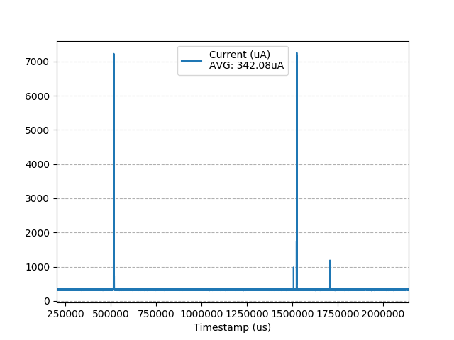
$ example.bat
Programming: C:\Users\Daniel\workspace\ppk_api\data\0_vanilla_ble_app_beacon.hex
Average: 628.64uA
Programming: C:\Users\Daniel\workspace\ppk_api\data\1_dcdc_enabled_ble_app_beacon.hex
Average: 419.18uA
Programming: C:\Users\Daniel\workspace\ppk_api\data\2_increase_adv_int_dcdc_enabled_ble_app_beacon.hex
Average: 342.08uA
The difference between the vanilla hex file and the one with the DCDC converter enabled is a 209uA reduction -- about a third. A further 77uA is saved when the advertising interval is increased by an order of magnitude. If these results needed to be processed further then the "data" directory now contains .CSV files with the raw data measurements along with .PNG graphs that would make nice additions to test reports.
Conlusion
Automating the tasks of using nrfjprog to push firmware to a DUT and then measuring its performance with the PPK can add valuable artifacts to build systems. In addition to measuring average current the ppk_api can also capture "trigger buffers" that illustrate periods of high current draw. And to make integration easier the ppk_api even has a --json option that makes its stdout output easier to parse.
-

wlgrd
-
Cancel
-
Vote Up
0
Vote Down
-
-
Sign in to reply
-
More
-
Cancel
Comment-

wlgrd
-
Cancel
-
Vote Up
0
Vote Down
-
-
Sign in to reply
-
More
-
Cancel
Children