


The nRF9160 is an exciting addition to Nordic's lineup of processors and radios. Ever since the announcement of a Nordic cellular product, I was chomping at the bit to dive in. And boy, did I get that opportunity!
In this post, I'll break down some of the most important examples that you can use with any nRF9160 based device. If you want to learning the ins and outs of the nRF Connect SDK this is a great first stop. By the end you should have a good understanding of the nuances of Zephyr and its capabilities..
For the duration of this post, I'll be using the nRF9160 Feather as a the hardware for getting started. It's a pre-certified development board you can use to build your products faster. It uses Nordic's nRF9160 cellular module which has GPS, Cat M1 LTE, NB-IoT and more. It runs Nordic's nRF Connect SDK which uses the Zephyr RTOS. The nRF9160 Feather has seen a successful launch on Hackster.io. Since then, hundreds of embedded developers across the world are using the nRF9160 Feather for their projects.
As for me, i'm Jared Wolff the owner of Circuit Dojo. I've been developing on Nordic technology since 2013 bringing countless products to market. I'm also the creator of the nRF9160 Feather. Having used it for over 6 months, I'm excited to share more about the nRF9160, nRF Connect SDK and Zephyr.
I modified following examples for use on the nRF9160 Feather. Several are from the nRF Connect SDK or the Zephyr SDK. Many thanks and all credit for those examples go to the authors. If you're following along, make sure that you have the prerequisites set up. More details on the process in the nRF9160 Feather documentation.
Using the LED
The nRF9160 Feather has a built in LED connected to the D7 pin (AKA P0.3 on the nRF9160 AKA Digital Pin 7). On most Arduino boards, D13 also toggles the onboard LED.
One of the easiest ways to understand how to use the LED is by using a modified version of Zephyr's blinky example:
Change directories to nrf9160-feather/samples/blinky and build the example with:
Bash:
 $ west build -b circuitdojo_feather_nrf9160ns
You can program the example using the newtmgr CLI:
Bash:
$ newtmgr -c serial image upload build/zephyr/app_update.bin
Once programed, hit the reset button on your nRF9160 Feather. The blue LED should start blinking!
Dissecting the code
This example uses entries in the board definitions for the nRF9160 Feather. Taking a look at circuitdojo_feather_nrf9160_common.dts (located in /zephyr/boards/arm/circuitdojo_feather_nrf9160ns). Here are the key ones for this example:
/* These aliases are provided for compatibility with samples */
	aliases {
		led0 = &blue_led;
		pwm-led0 = &pwm_led0;
		sw0 = &button0;
	};
led0 is what we're after. Though sw0 will be handy in a bit..
In your main.c you can use this definitions with the DT_ALIAS DT_GPIO_LABEL and DT_GPIO_PIN macros. This allow you to "look up" the LED0 pin and use it within your application as a device.
#include <device.h>

#define LED0_NODE DT_ALIAS(led0)
#define LED0	DT_GPIO_LABEL(LED0_NODE, gpios)
#define PIN	DT_GPIO_PIN(LED0_NODE, gpios)
Finally, during initialization we'll grab the freshly created LED0. This will allow you to configure the device. First getting the device itself and the configuring it using gpio_pin_configure.
void main(void)
{
	struct device *dev;
	int ret;

	dev = device_get_binding(LED0);
	if (dev == NULL) {
		return;
	}

	ret = gpio_pin_configure(dev, PIN, GPIO_OUTPUT_ACTIVE);
	if (ret < 0) {
		return;
	}

	/* Do stuff! */
}
In the case above, GPIO_OUTPUT_ACTIVE will configures the pin as an output and ****sets it high. This effectively kills two (metaphorical) birds with one stone.
Then using the gpio_pin_set function you can turn on and off the pin from anywhere in your code.
gpio_pin_set(dev, PIN, 1);
Handy no?
Using the Button
Using the button is very similar to the LED case except we're reading from a GPIO instead of writing. In this example i'll show you how to use a callback when a button press occurs
Just like the earlier example, change directories to nrf9160-feather/samples/button. Then, build using the build command:
Bash:
$ west build -b circuitdojo_feather_nrf9160ns
You can complete programming with the newtmgr CLI:
Bash:
$ newtmgr -c serial image upload build/zephyr/app_update.bin
Once programed, hit the reset button on your nRF9160 Feather. Open up LTE Link Monitor and make sure you get text output when you press the button.
Bash:
*** Booting Zephyr OS build v2.3.0-rc1-ncs1-2410-g7d20f2ebf259  ***
Set up button at GPIO_0 pin 12
Set up LED at GPIO_0 pin 3
Press the button
Button pressed at 71268
Button pressed at 82324
Button pressed at 89951
Button pressed at 153706
In this example, the blue LED illuminates when you press the mode button.
Dissecting the code
If you're looking to use this functionality in your own code, here's the breakdown on how to do it.
First, you'll need to define the switch using these macros.
#include <device.h>

#define SW0_NODE DT_ALIAS(sw0)
#define SW0_GPIO_LABEL DT_GPIO_LABEL(SW0_NODE, gpios)
#define SW0_GPIO_PIN DT_GPIO_PIN(SW0_NODE, gpios)

/* Callback data */
static struct gpio_callback button_cb_data;
Then you can initialize your button like so:
static void button_init()
{
    struct device *button;
    int ret;

    button = device_get_binding(SW0_GPIO_LABEL);
    if (button == NULL)
    {
        LOG_ERR("Error: didn't find %s device\\n", SW0_GPIO_LABEL);
        return;
    }

    ret = gpio_pin_configure(button, SW0_GPIO_PIN, SW0_GPIO_FLAGS);
    if (ret != 0)
    {
        LOG_ERR("Error %d: failed to configure %s pin %d\\n",
                ret, SW0_GPIO_LABEL, SW0_GPIO_PIN);
        return;
    }

    ret = gpio_pin_interrupt_configure(button,
                                       SW0_GPIO_PIN,
                                       GPIO_INT_EDGE_TO_ACTIVE);
    if (ret != 0)
    {
        LOG_ERR("Error %d: failed to configure interrupt on %s pin %d\\n",
                ret, SW0_GPIO_LABEL, SW0_GPIO_PIN);
        return;
    }

    gpio_init_callback(&button_cb_data, button_pressed, BIT(SW0_GPIO_PIN));
    gpio_add_callback(button, &button_cb_data);
    LOG_INF("Set up button at %s pin %d\\n", SW0_GPIO_LABEL, SW0_GPIO_PIN);
}
This will create the button and add a callback when the button is pressed. Here's what the callback looks like:
static void button_pressed(struct device *dev, struct gpio_callback *cb,
                           uint32_t pins)
{
    printk("Button pressed at %" PRIu32 "\\n", k_cycle_get_32());
}
In the case above, it will print out a message with the number of ticks have occurred since the start of the program. Note: since this is a 32bit number it eventually does roll over and start at 0 again.
Battery Measurements
Measuring the battery voltage is one way to approximate how much charge your battery has. It's not the best way but it usually gets the job done in most cases.
You can use battery.c and battery.h (originally from zephyr/samples/boards/nrf/battery/src/) to get started with measuring your battery's voltage. Include the files into your application then create your own batt_measure() function:
#include "battery.h"

void batt_measure()
{

    // Add battery measurement
    int rc = battery_measure_enable(true);
    if (rc != 0)
    {
        LOG_ERR("Failed initialize battery measurement: %d\\n", rc);
        return;
    }

    int batt_mV = battery_sample();

    if (batt_mV < 0)
    {
        LOG_ERR("Failed to read battery voltage: %d\\n",
                batt_mV);
    }
    else
    {
        LOG_INF("Battery: %d mV", batt_mV);
    }

    battery_measure_enable(false);
}
This enables the onboard load switch using battery_measure_enable(true) to take a battery measurement. This switch prevents leakage during the standby state. (VBAT/200k becomes a big deal when you want your nRF9160 Feather to last years on batteries!)
You can use the reading in mV to interpolate approximate charge. Remember that the charger is always on. This means it will keep VBAT as close to 4.2V as possible when USB is connected. With that said, it's not a good way to know if the battery is disconnected.
You can find a working example in nrf9160-feather/samples/battery. No modifications are necessary. Simply run:
Bash:
cd nrf9160-feather/samples/battery
west build -b circuitdojo_feather_nrf9160ns
Then load it in DFU mode using
Bash:
newtmgr -c serial image upload build/zephyr/app_update.bin
Using the power latch and ultra deep sleep
There are a few ways to keep the nRF9160 Feather powered during operation. If take a look at the schematic, you can see the power supply can be enabled in several ways.
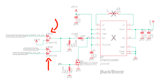
One of the most important is the NRF_PS_EN signal. When you insert USB or hit the MODE button, the nRF9160 powers up and asserts that line high. This mains power supply operation with battery even if you've removed USB. There's nothing extra you need to do to make this work. It's built directly into every example built with the circuitdojo_feather_nrf9160ns board definition!
If you'd like to come full circle and deactivate that signal for ultra deep sleep (ie. shutdown), we'll have to add some extra code.
First we'll need some way of controlling this pin. The mode button is a perfect way to do that. So we'll utilize the mode button for the first step in the process. Similarly to the button example above we'll need to set it up first. I've place this code in my main function:
int ret;

gpio = device_get_binding(GPIO0);
if (gpio == NULL)
{
	printk("Error: unable to get gpio device binding.\\n");
	return;
}

button = device_get_binding(SW0_GPIO_LABEL);
if (button == NULL)
{
	printk("Error: didn't find %s device\\n", SW0_GPIO_LABEL);
	return;
}

ret = gpio_pin_configure(button, SW0_GPIO_PIN, SW0_GPIO_FLAGS);
if (ret != 0)
{
	printk("Error %d: failed to configure %s pin %d\\n",
					ret, SW0_GPIO_LABEL, SW0_GPIO_PIN);
	return;
}

ret = gpio_pin_interrupt_configure(button,
																		SW0_GPIO_PIN,
																		GPIO_INT_EDGE_TO_INACTIVE);
if (ret != 0)
{
	printk("Error %d: failed to configure interrupt on %s pin %d\\n",
					ret, SW0_GPIO_LABEL, SW0_GPIO_PIN);
	return;
}

gpio_init_callback(&button_cb_data, button_pressed, BIT(SW0_GPIO_PIN));
gpio_add_callback(button, &button_cb_data);
printk("Set up button at %s pin %d\\n", SW0_GPIO_LABEL, SW0_GPIO_PIN);
This adds the support for detecting a button press and points to the callback function. That function will help us know that the button is pressed!
Speaking of the button callback, here's what the callback looks like:
void button_pressed(struct device *dev, struct gpio_callback *cb,
										u32_t pins)
{
	printk("Button pressed at %" PRIu32 "\\n", k_cycle_get_32());

	/* Schedule work for 2 seconds to see if the button is still pressed */
	k_delayed_work_submit(&button_press_work, K_SECONDS(2));

	/*Set LED on*/
	gpio_pin_set(led, LED0_GPIO_PIN, 0);
}
I'm using the callback to do two things here:
- Schedule a worker function to execute in about 2 seconds. The function is used to check if the button is still pressed.
- Turn on the LED (connected to D7) for some visual feedback to the user.
Work functions are useful for one-off tasks. (It's a key functionality of Zephyr!) It also allows you to call code that may invoke a mutex which you can't do in an interrupt context. Additionally, these functions use the system work queue which has a fairly low thread priority. This ensures that your code plays nicely with the rest of the system.
You can set up a worker by initializing at the top of your .c file:
/* Worker for checking button after 2 seconds */
static struct k_delayed_work button_press_work;
There are two types of workers: workers that you can delay and workers that execute immediately. You initialize them slightly differently but the concept is the same. For more information on the concept check out the Zephyr notes on Workqueue Threads. In this case I used a delayed worker.
You can initialize a worker by referencing the worker and associating the work function.
/* Init work function */
k_delayed_work_init(&button_press_work, button_press_work_fn);
In the case of this example, here's what the work function looks like for this example:
static void button_press_work_fn(struct k_work *item)
{
	bool pressed = false;

	if (gpio_pin_get(button, SW0_GPIO_PIN) == 0)
		pressed = true;

	printk("Still pressed: %s\\n", pressed ? "true" : "false");

	/* Turn off LED */
	gpio_pin_set(led, LED0_GPIO_PIN, 1);

	/* Wait until it's  not pressed */
	while (gpio_pin_get(button, SW0_GPIO_PIN) == 0)
		;

	/*Shut er down.*/
	if (pressed)
	{

		/* Turn off latch pin */
		gpio_pin_set_raw(gpio, POWER_LATCH_PIN, 0);

		/* Wait infinitely */
		for (;;)
			;
	}
}
This function checks the button and if pressed will wait until release to turn off the nRF9160 Feather. The device will go into a "shutdown" state where the only device active is the onboard RTC.
You can use this example by
- programming the example via
[newtmgr](<https://docs.jaredwolff.com/nrf9160-programming-and-debugging.html#booloader-use>) - plugging in a battery and
- using the Mode (MD) button to turn the nRF9160 Feather on and off.
Note: when turning on from a cold start, the button press will activate the bootloader. Pressing the Reset button will allow the main code to execute. I will fixe this in future versions of the bootloader.
The full working code can be found in nrf9160-feather/samples/deep_sleep:
Bash:
cd nrf9160-feather/samples/deep_sleep
west build -b circuitdojo_feather_nrf9160ns
Then load it in DFU mode using
Bash:
newtmgr -c serial image upload build/zephyr/app_update.bin
Setting a Timer Using The External RTC
A while back I covered creating drivers on Zephyr. The inspiration? The RTC chip onboard the nRF9160 Feather.
While the Zephyr repo had some RTC implementations they did not have the one I needed. So, in this section we'll concentrate on using the out-of-tree driver for the PCF85063A RTC.
You can find the driver in nrf9160-feather/drivers. In order to use it will have to set CONFIG_PCF85063A and place it in your prj.conf:
# RTC
CONFIG_PCF85063A=y
Within your main.c you can then initialize it like so:
#ifdef CONFIG_PCF85063A
static void rtc_init()
{

	// Get the device
	rtc = device_get_binding("PCF85063A");
	if (rtc == NULL)
	{
		LOG_ERR("Failed to get RTC device binding");
		return;
	}

	LOG_INF("device is %p, name is %s", rtc, log_strdup(rtc->name));

	// 10 seconds
	const struct counter_alarm_cfg cfg = {
			.ticks = 10,
	};

	// Set the alarm
	int ret = counter_set_channel_alarm(rtc, 0, &cfg);
	if (ret)
	{
		LOG_ERR("Unable to set alarm");
	}
}
#endif
Notice how I wrapped rtc_init with a macro? That way if you're not using the RTC it won't get included at all in your code. It's a very cheap way of reducing your code size when you don't need certain peripherals.
In the above, you can see that I set the ticks to 10 seconds. In seconds mode, you can wait up to 255 seconds. In a slower mode you can set a timer for up to 15300 seconds! Once started, you can use the counter_get_pending_int function to poll for any changes.
int ret = counter_get_pending_int(rtc);
LOG_INF("Interrupt? %d", ret);

if (ret == 1)
{
	timer_flag = true;

	int ret = counter_cancel_channel_alarm(rtc, 0);
	if (ret)
	{
		LOG_ERR("Unable to cancel channel alarm!");
	}
}
The code above checks the interrupt flag and clears it once completed. Since there are no free GPIOs on the nRF9160 Feather, the interrupt pin isn't accessible. However, it still powers the device on an alarm event waking up your device from sleep. Boot is an opportune time to check for changes on the external RTC and clear the flags as necessary.
You can compile and load the full working example for the nRF9160 Feather like so:
Bash:
cd nrf9160-feather/samples/external_rtc
west build -b circuitdojo_feather_nrf9160ns
Then load it in DFU mode using
Bash:
newtmgr -c serial image upload build/zephyr/app_update.bin
Sending SMS
One of the cooler and more familiar features of the nRF9160 Feather is the ability for it to send SMS messages! Sending an SMS message is as simple as invoking a few AT commands to the nRF9160 Feather modem firmware. The only drawback is that your nRF9160 Feather must have the v1.1.2 or newer modem firmware installed (A.K.A MFW v1.2.2). Theres a full section in the nRF9160 Feather documentation about how to update the modem firmware.
A great way to start with SMS is the provided example within the nrf9160-feather/samples/sms/ directory. Let's dissect what's inside:
One of the most important things you'll see is at_commands. These commands are the commands you'll get familiar with in order to send a message. They look like gibberish, but I promise you they're important!
const char *at_commands[] = {
		"AT+CNMI=3,2,0,1",
		"AT+CMGS=21\\r0001000B912131445411F0000009C834888E2ECBCB21\\x1A",
		/* Add more here if needed */
};
The first line readies the nRF9160 Feather to send an SMS. While the second is the message itself. Text messages use a special encoding which don't make them terribly easy for a human to read. In the case above, the above message will look something like this to the receiver:

But how do we control or generate this special format? Currently there is no built-in PDU encoder in Zephyr/nRF Connect SDK. You can use an external one like this one to generate your messages though!
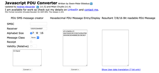
To get the correct format, update the Receiver text box with the target phone number. Then update your message and hit Convert. It will spit out the encoded message. This command relies heavily on special characters, you need to make sure that they do not get removed. In particular, you need to have a carriage return (\\r) after AT+CMGS=21 and \\x1A must be always at the end of the message. Again, check out the at_commands array above to see exactly how it looks like.
The rest of the sms is very similar to the button and deep_sleep examples. The idea being is that when you press the button, you'll invoke the AT commands using a work function. Here's the work function that gets called when you press the Mode button:
/* Work for starting sms commands*/
static void sms_work_fn(struct k_work *work)
{
	for (int i = 0; i < ARRAY_SIZE(at_commands); i++)
	{
		int err;
		enum at_cmd_state cmd_state = AT_CMD_OK;

		printk("%s\\r\\n", at_commands[i]);

		if ((err = at_cmd_write_with_callback(at_commands[i],
																					at_cmd_handler,
																					&cmd_state)) != 0)
		{
			printk("Error sending: %s. Error: %i. State: %i.", at_commands[i], err, (int)cmd_state);
		}
	}

	/* Run SMS work */
	/* k_delayed_work_submit(&sms_work, K_SECONDS(300)); */
}
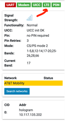
The sms_work_fn iterates through all the commands and sends them to the modem. Remember that this example does not connect automatically. It's best used in nRF Connect Desktop's LTE Link Monitor but you'll need to issue a AT+CFUN=1 command. You should wait until the LTE icon turns green or the network name gets highlighted in yellow before hitting the mode button.
You can compile and load the full working example for the nRF9160 Feather like so:
Bash:
cd nrf9160-feather/samples/sms
west build -b circuitdojo_feather_nrf9160ns
Then load it in DFU mode using
Bash:
newtmgr -c serial image upload build/zephyr/app_update.bin
Using External Flash
Another capability of Zephyr is it's pre-built support for external flash over SPI. Configuring the external flash and filesystem for the nRF9160 Feather crazy easy.
First, let's take a look at what needs to be added to the prj.conf. We'll be looking at the example in nrf9160-feather/samples/external_flash/.
# SPI Flash
CONFIG_SPI=y
CONFIG_SPI_NOR=y
CONFIG_SPI_NOR_FLASH_LAYOUT_PAGE_SIZE=4096

# Enable flash operations.
CONFIG_FLASH=y
CONFIG_FLASH_MAP=y
CONFIG_FLASH_PAGE_LAYOUT=y

# Enable the LittleFS file system.
CONFIG_FILE_SYSTEM=y
CONFIG_FILE_SYSTEM_LITTLEFS=y

# Nordic specific external flash stuff
CONFIG_PM_EXTERNAL_FLASH=y
CONFIG_PM_EXTERNAL_FLASH_DEV_NAME="W25Q32JV"
CONFIG_PM_EXTERNAL_FLASH_BASE=0x0
CONFIG_PM_EXTERNAL_FLASH_SIZE=0x2000000
There's a lot here but it makes things simple when you want to use the device itself. The first chunk relates to enabling SPI. SPI is the interface we're using to talk to the onboard W25Q32JV flash chip.
Next, we need to enable flash operations. You can use the flash manually but you' also have to take into account for flash wear and more. A filesystem like LittleFS makes your life easier on that aspect!
Finally, the last chunk relates to the use of external flash and the nRF91. In order to address the flash using the device tree, you'll need to add CONFIG_PM_EXTERNAL_FLASH to prj.conf.
Now that we've addressed prj.conf we'll need to chat about another important aspect of the example in nrf9160-feather/samples/external_flash/: the .overlay file. The purpose of an overlay file is to update certain aspects of the board definition. In our case? It allows us to update the flash information to the W25Q32JV. Originally when I had created the board definitions, I was planning on using the W25Q16JV. All examples using the external flash, as of this writing, will need this overlay file:
/*
 * Copyright (c) 2020 Circuit Dojo LLC
 *
 * SPDX-License-Identifier: Apache-2.0
 */

/delete-node/ &w25q16jv;

&spi3 {
	compatible = "nordic,nrf-spim";
	status = "okay";
	sck-pin = <11>;
	mosi-pin = <9>;
	miso-pin = <28>;
	cs-gpios = <&gpio0 7 GPIO_ACTIVE_LOW>;
	w25q32jv: w25q32jv@0 {
		compatible = "jedec,spi-nor";
		label = "W25Q32JV";
		reg = <0>;
		spi-max-frequency = <40000000>;
		wp-gpios = <&gpio0 8 GPIO_ACTIVE_LOW>;
		hold-gpios = <&gpio0 10 GPIO_ACTIVE_LOW>;
		size = <0x2000000>;
		has-dpd;
		t-enter-dpd = <4000>;
		t-exit-dpd = <25000>;
		jedec-id = [ef 40 16];
		has-be32k;
	};
};
The above contents should be placed in boards/circuitdojo_feather_nrf9160ns.overlay of your project.
Finally within main.c itself we'll enable include some important header files:
#include <fs/fs.h>
#include <fs/littlefs.h>
#include <storage/flash_map.h>
And add the config for external flash:
FS_LITTLEFS_DECLARE_DEFAULT_CONFIG(storage);
static struct fs_mount_t lfs_storage_mnt = {
		.type = FS_LITTLEFS,
		.fs_data = &storage,
		.storage_dev = (void *)FLASH_AREA_ID(external_flash),
		.mnt_point = "/lfs",
};
FLASH_AREA_ID(external_flash) is the most important parameter here. This indicates the "device" that Zephyr will target and use.
In the remainder of the example code, main() opens an prepares the filesystem (if necessary). Then it increments the value of the boot_count file every time the device starts up. Here's the actual increment process:
  rc = fs_stat(fname, &dirent);
	printk("%s stat: %d\\n", fname, rc);
	if (rc >= 0)
	{
		printk("\\tfn '%s' siz %u\\n", dirent.name, dirent.size);
	}

	struct fs_file_t file;

	rc = fs_open(&file, fname);
	if (rc < 0)
	{
		printk("FAIL: open %s: %d\\n", fname, rc);
		goto out;
	}

	u32_t boot_count = 0;

	if (rc >= 0)
	{
		rc = fs_read(&file, &boot_count, sizeof(boot_count));
		printk("%s read count %u: %d\\n", fname, boot_count, rc);
		rc = fs_seek(&file, 0, FS_SEEK_SET);
		printk("%s seek start: %d\\n", fname, rc);
	}

	boot_count += 1;
	rc = fs_write(&file, &boot_count, sizeof(boot_count));
	printk("%s write new boot count %u: %d\\n", fname,
				 boot_count, rc);

	rc = fs_close(&file);
	printk("%s close: %d\\n", fname, rc);
Though this example is simple, you can use these exact calls and concepts to write and read from external flash. Plus, on top of it, Zephyr and Nordic have don't most of the work for you. There's no futzing with drivers, there's no testing. It just works. 
You can compile and load the full working example for the nRF9160 Feather like so:
Bash:
cd nrf9160-feather/samples/external_flash
west build -b circuitdojo_feather_nrf9160ns
Then load it in DFU mode using
Bash:
newtmgr -c serial image upload build/zephyr/app_update.bin
Publishing GPS
In this final section we'll cover the usage of GPS on the nRF9160. While it appears to be a "simple" feature on the outside there's a ton going on behind the scenes. Take a look at the gps example in nrf9160-feather/examples/gps. It's modified specifically for use with the nRF9160 Feather. If you do find yourself using GPS in another project, this is a useful reference to get you running quickly. Most importantly, and easily forgotten, make sure you set the COEX0 settings. You can accomplish this using an AT command or in the prj.conf
#define AT_COEX0 "AT\\%XCOEX0=1,1,1570,1580"
COEX0 turns the GPS on and off during periods where the LTE radio is not in use. If this feature did not exist, the LTE radio could saturate the receiver on the GPS rendering it useless.
If you're using the nRF9160 GPS module (enabled in prj.conf with CONFIG_NRF9160_GPS) you can also enable this option using:
CONFIG_NRF9160_GPS_SET_COEX0=y
CONFIG_NRF9160_GPS_COEX0_STRING="AT%XCOEX0=1,1,1565,1586"
You can see a full example of this in action in the AGPS example. More details about getting that compiled and running in the nRF9160 Feather documentation.
I you look further down in main.c of the example you'll see the familiar at_commands. You'll also see that it includes the COEX0 command from above..
static const char     at_commands[][31]  = {
				AT_XSYSTEMMODE,
#ifdef CONFIG_BOARD_NRF9160DK_NRF9160NS
				AT_MAGPIO,
				AT_COEX0,
#endif
#ifdef CONFIG_BOARD_CIRCUITDOJO_FEATHER_NRF9160NS
				AT_COEX0,
#endif
				AT_ACTIVATE_GPS
			};
Within the main function of the example, you can see some references to a SUPL library. SUPL allows the device to download supplemental GPS data to bootstrap getting a fix faster. This is similar to how your cellphone can get an almost instant GPS fix. Without the library though? It may take longer. I've seen anywhere from 30 seconds to 90 seconds on a cold boot.
The biggest caveat to the SUPL library? You'll need to connect to LTE to get that data. To use the SUPL library you'll have to agree to the license and download the code on Nordic's site. More details are here.
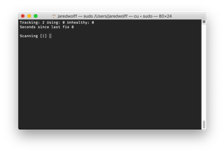
Without SUPL, the example only calls one other function in main(): process_gps_data. It reaches into the modem firmware to see if there is any new results from an ongoing GPS scan. Open a terminal connection (more info on both in the docs) you'll see a nice output that updates during the fix process:
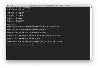
Once a fix does occur you'll get the full details on the screen:
You can get going with example by building with
Bash:
cd nrf9160-feather/samples/gps
west build -b circuitdojo_feather_nrf9160ns
Then load it in DFU mode using
Bash:
newtmgr -c serial image upload build/zephyr/app_update.bin
For more details check out the code in nrf9160-feather/samples/gps.
Conclusion
In this post we covered some of the most important pieces of functionality of the nRF9160. Plus, you've learned how to navigate the nRF Connect SDK and Zephyr. While there is lots more, this should give you a better understanding of how to structure your Zephyr projects. Feel free to grab an use any of these examples since they have a permissive license!
Looking to learn more about the nRF9160 Feather? Check out this page. The documentation and design is also 100% open. Also be sure to check out the product page for the nRF9160 here. You can find full documentation on the nRF Connect SDK here.
Have more questions? Head on over to the nRF9160 Feather community page and I'll try to help the best I can! Have a more specific nRF9160 or nRF Connect SDK question? Nordic's Devzone is a great place for that as well!
-
$core_v2_ui.GetResizedImageHtml($comment.User.AvatarUrl, 44, 44, "%{border='0px', alt=$comment.User.DisplayName, ResizeMethod='ZoomAndCrop'}")
$core_v2_ui.UserPresence($comment.User.Id)
$comment.User.DisplayName
-
Cancel
-
Vote Up
$currentVotes.ToString("+0;-0;0")
Vote Down
-
$core_v2_ui.Like($comment.CommentId, $comment.CommentContentTypeId, "%{ Format = $likeFormat, IncludeTip = 'true' }")
-
Sign in to reply
-
More
-
Cancel
Children