This post is older than 2 years and might not be relevant anymore
More Info: Consider searching for newer posts

How use usb data line without usb core

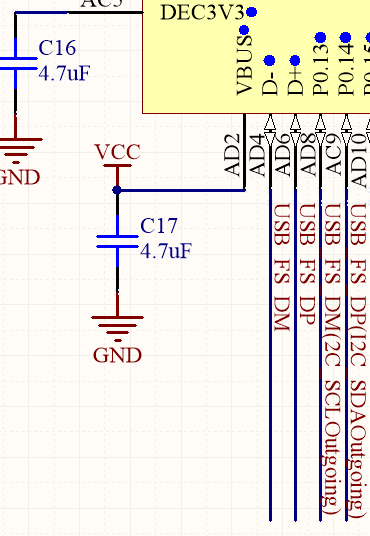
Hi, Nordic! We have connected gpio pins to usb data line pins for using usb or i2c in different times. But even if USB core disconnected, usb lines hinder for i2c lines. Is it possible connect usb d+ and d- to GPIO?

usb i2c connection

  • What do you mean you have "connected gpio pins to USB pins"? The circuit diagram makes it look as though you've connected USB D+ both to the D+ pin and to a random GPIO. Why have you done this? The D+/D- pins can only be used for USB and nothing else and no other GPIOs can take a USB signal so it's hard to understand what you're trying to accomplish.

  • We want use usb connector for usb and for i2c.

    First case: connecting board to usb host via usb

    Second case: connecting board to another board via i2c

    Both case used one usb connector(GND, VCC, D+ and D-), but for i2c D+ changed to SDA and D- to SCL.

  • Hello Vlad

    As RK has stated none of the GPIO of the nRF52840 supports USB, and the USB pins are exclusively used for USB. So if you want to use the GPIO for USB do that you would have to bitbang it somehow, though I'm not sure if that would be possible.

    Unfortunately we do not have any examples or reference code for something like this. I have seen people claim to have bitbanged USB on ARM M0 processors, however for our products you would have to worry about the SoftDevice using part of the processor time as well.

    To my knowledge USB has never been bitbanged on any of our products, so I'm afraid I don't have any further advice on how to achieve something like that.

    Best regards

    Jørn Frøysa

  • so I finally, after the comment from yesterday, understand what they are trying to do. They aren't trying to use GPIOs for USB. What they're trying to do is have one connector on the board, a USB connector, but have it work both for USB (usual case, usual wiring) or I2C (with some custom connector). So they have D+/D- on the connector hooked up to D+/D- pads on the chip but also to two GPIOs for when they're using the USB connector for I2C. I think what they hoped for /expected is that if the USB module itself is off, the D+/D- pads would be high impedence and wouldn't interfere with the I2C communication going into the GPIO pins. I assume when using USB,they set the GPIOs high impedence and that works. So I guess the question here is what are the electrical characteristics of the D+/D- pads when the USB module is turned off?

  • Ah yes of course, I believe you're right. I will look further into this.

Related