This post is older than 2 years and might not be relevant anymore
More Info: Consider searching for newer posts

NRF52832 - Monopole Antenna on 24mm Dia PCB

Hi,

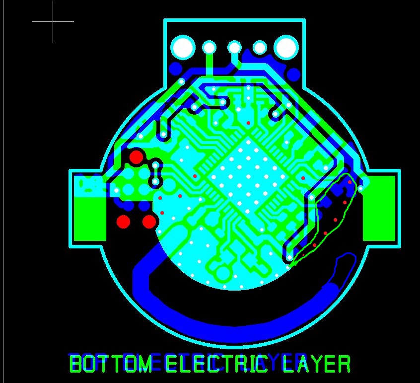
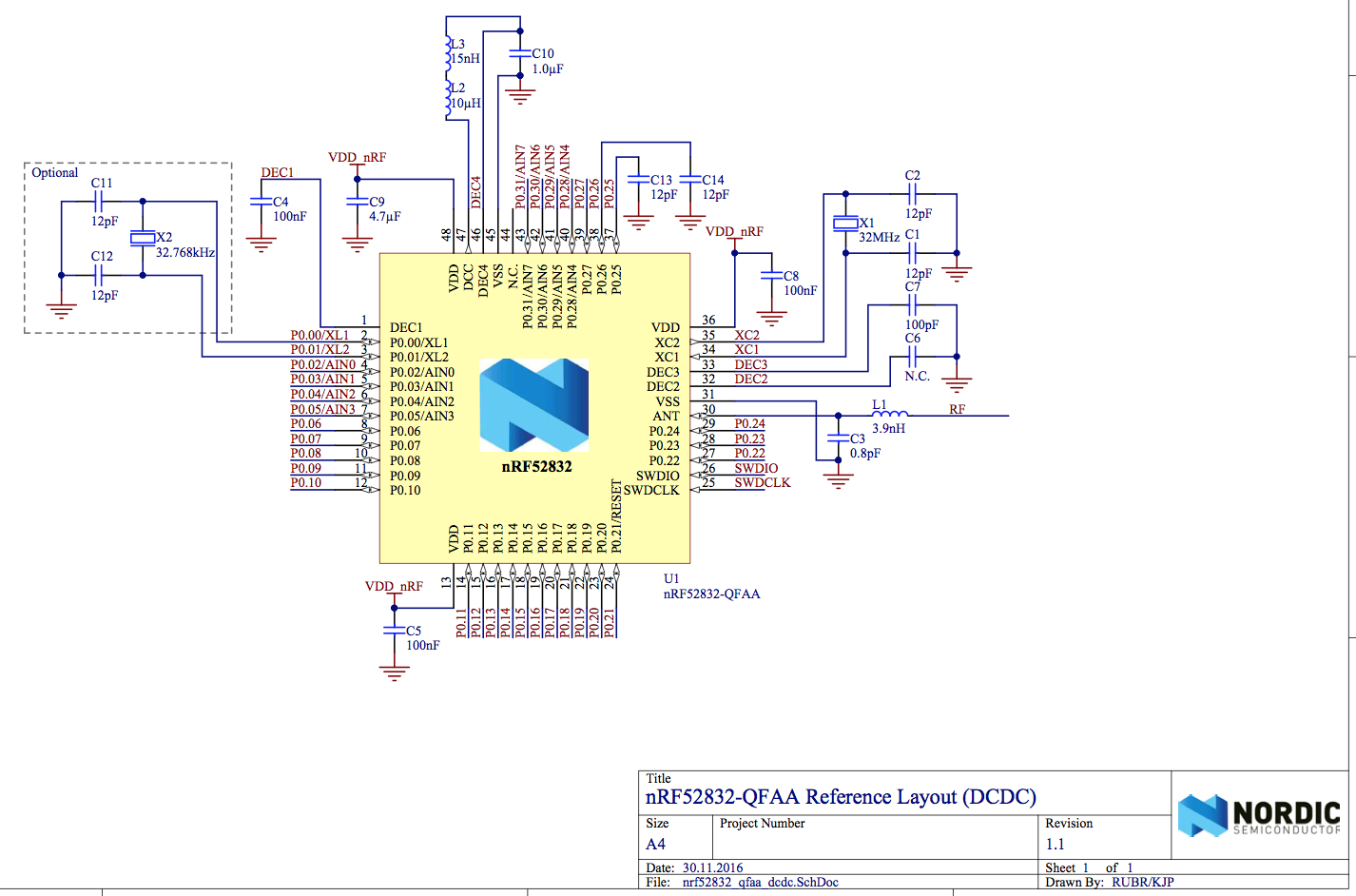
I need to design a small nRF52 board On 24mm Dia 2-layer PCB, same like nRF51822 Bluetooth Smart Beacon Kit (nRF51822 Coin-Cell design). Please find the attached Schematics and layout files for your reference.

For mono-pole antenna,Layout Reference taken from nRF51822 Coin-Cell design, and rest from the nRf52 DK ref design especially in the case of the antenna matching circuitry (components between device pin ANT and the antenna).

I am looking for a range of around 40-50 meters. Please review and let me know any suggestions to achieve best performance of the antenna. Thank you very much for your time and if you need any more information, I will gladly supply it..

NRF52832 Schematics.pdf

Gerber.zip

NRF52832-ERAATA-138.png

  • @bhaskar-ece: In order to properly review your layout I need to look at the Gerber files. Could you attach them to your question?

  • Hi bjorn-spockeli, I have uploaded Gerber files... Please review and let me know any suggestions to achieve best performance of the antenna. Thank you very much for your time and if you need any more information, I will gladly supply it..

  • C3 and C4 and C17 should be a 100nF and not 0.1 uF. I see that you have grounded P0.25 and P0.26, but its the VSS (pin 44)that needs to be connected to ground with a via as close as possible. You also need a via to ground close to the ground pad of the C2 cap.

  • Thank you very much for your review and suggestions.I thought 0.1uF is same as 100nF but let me know any special type of parameters to be considered while selecting these capacitors . Please find the attached NRF52832 schematics of errata 138. I noticed you have added capacitor C13 and C14 (12pF) caps. However, they are not visible on Info-center's reference circuitry and I don't use P0.25 and P0.26 ports in my design,hence simply grounded on layout by connecting them to the center pad to save the space and cost. Let me know if it's wrong? and you told pin44 needs to be connected to ground but by default Pin44 is N.C. and physically there no functionality associated with the same and still it needs to be connected to GND? Let me know if my assumption is wrong?... Thank you...

  • Hi Bhaskar, you are completely correct, 100nF == 0.1uF, . Again, you are correct, those pins should be grounded according to erata 138. I stated pin 44, but meant pin 45, which should be connected to the same ground plane as the ground pad of C2. However, it might not be strictly necessary. After discussing your layout with a colleague I would recommend extending the ground plane past D1 by moving the power line a bit in and then adding more vias at the red dots, see the attached screenshot. Furthermore I would also extend the antenna by 2-3mm as this is going to be handy when you're tuning the antenna by cutting in order to adjust the length image description

Related