
I was wondering if anyone has done any extremely high speed UART work on the nRF51 (or the non-EasyDMA module on the nRF52). I need to improve performance for an existing prototype that has to stream a large amount of data over UART (and frame it, and run the existing application...)
I have reliable communciations running with flow control at 1Mbaud, but I'm trying to reduce overhead on the RX/TX ISRs to provide extra cycles to the framing/deframing code and improve actual data rate. I'm already inlining virtually all of my code, and using my own UART libraries. The biggest improvement I see right now is to reduce ISR calls, by utilizing as much of the HW buffers as possible. This is easy with the RX buffer of course.
In my investigations, I noticed that the UART TX buffer depth is actually more than documented - you can actually stuff 3 bytes in, and those same 3 bytes will come out. Of course, this causes all sorts of critical code issues with the lack of a real TX empty or TX full ISR - so I was thinking about using PPI to trigger a timer after the first TXREADY interrupt (after stuffing anywhere from 1-3 bytes), to guarantee that the buffer must be empty, before attempting to stuff up to 3 bytes again. Anyone have experience or comments on this technique?
I've seen the nRF52 UARTE, and it's absolutely wonderful and would solve all of my problems (well, that, the M4 core, and the 4x clock speed), but unfortunately I'm stuck developing code for nRF51 hardware this time. Porting is also a bit of work, because there's some extremely non-portable clock-cycle-sensitive assembler code I had to write for the nRF51, and at the moment it sounds like a few days of careful optimization is going to be the faster strategy.
Edit 7/23/2017: Here's some test code I used (this is in main):
_DBG_INIT();
NRF_UART0->PSELTXD = HAL_UART_PIN_TXD;
NRF_UART0->PSELRXD = HAL_UART_PIN_RXD;
NRF_UART0->PSELRTS = HAL_UART_PIN_RTS;

NRF_UART0->CONFIG = (UART_CONFIG_HWFC_Enabled << UART_CONFIG_HWFC_Pos);

NRF_UART0->BAUDRATE = (UART_BAUDRATE_BAUDRATE_Baud1M
		<< UART_BAUDRATE_BAUDRATE_Pos);
NRF_UART0->ENABLE = (UART_ENABLE_ENABLE_Enabled << UART_ENABLE_ENABLE_Pos);
NRF_UART0->TASKS_STARTTX = 1;
NRF_UART0->TASKS_STARTRX = 1;
NRF_UART0->EVENTS_RXDRDY = 0;

_DBG_PROBE_A_BEGIN;
NRF_UART0->TXD = 0x80;
_DBG_PROBE_A_END;
_DBG_PROBE_A_BEGIN;
NRF_UART0->TXD = 0x03;
_DBG_PROBE_A_END;
_DBG_PROBE_A_BEGIN;
NRF_UART0->TXD = 0x50;
_DBG_PROBE_A_END;
_DBG_PROBE_A_BEGIN;
NRF_UART0->TXD = 0x5B;
_DBG_PROBE_A_END;
while (1);
Note that this was compiled on a device that had SoftDevice S110 7.2.0 (our legacy hardware also only has rev 2 chips onboard). Obviously the softdevice is not enabled in this test code, though nothing changes with it enabled. There is no UART ISR for enabled for this demonstration.
_DBG_INIT() and the _DBG_PROBE functions are just macros which set up and toggle GPIOs to allow me to probe and demonstrate timings. You can just replace these with nrf_gpio_set on your hardware to test this yourself. Similarly HAL_UART_PIN are just pin definitions, and switch them with appropriate pins in your hardware. This code continues to function (just without the logic analyzer traces to show the timings of the TXD writes) without those DBG lines.
Here's the output of a logic analyzer:
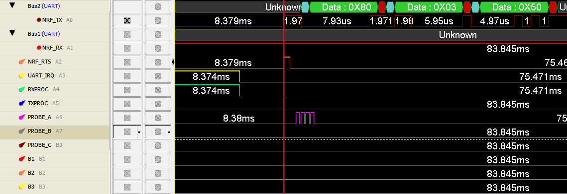
There is clearly no RAM buffer I'm using in my test code, and that the four writes to TXD clearly occur before the first byte is even written out (a pulse appears on PROBE_A for each TXD write) Only the first three bytes I write make it to the output, while the fourth just disappears. Ignore the RXPROC, TXPROC, IRQ, etc - I left those labels in from other testing, and do not imply that any other code is running alongside this test.
This might be useful to know for new designs as well, as I suspect it's the same back-end peripheral in the nRF52, in case someone can't use the UARTE for some reason.
Edit 7/23/2017 #2:
So here's what I'm planning on doing with the TX chain, to be clear: Using PPI, connect EVENTS_TXREADY to TASKS_START for one of the timers. EVENTS_COMPARE fires at least after 2 (or 3?) bytes are sent out (20/30us @ 1Mbaud), guaranteeing all three bytes are flushed. This ISR is the actual TX handler ISR, which pulls up to three bytes from the software FIFO buffer. EVENTS_COMPARE is then reset appropriately. Of course, there's also any necessary "dead" ISR andling code for when the buffer is empty.
The idea is that despite the lack of an appropriate event for an empty buffer on the UART (I believe EVENTS_TXREADY fires every time a byte is moved from the holding register to the transmit register from earlier testing), all of the transmit registers are guaranteed to be empty when this ISR fires. In fact, the lack of an appropriate event to use these extra registers in a meaningful way are why I assume the larger buffer is not documented (or is there something broken about this concept??). If there aren't enough bytes to transmit thrice in succession, there is extra latency and reduced efficiency, but that does not occur when maximum throughput is necessary.
Anyway, I'm interested in hearing if there's something broken with this logic, my test methodology, or perhaps if there's something else known to be broken with these extra bytes in the transmit buffer. I'll probably find out anyway in a day. I'm primarily concerned about any edge cases I may miss in my testbench that may cause the transmit chain or peripheral to suddenly die; an increased BER on the other hand due to occasional data corruption would not be the worst thing in the world, mainly because the higher level protocols are designed to handle bad frames.

