
 Hi,guys
In my project,I intend to generate 4 channels pwm,using 8 channel PPI,timer1,timer2. As below, the timer initializing and timer interrup handler code:
Hi,guys
In my project,I intend to generate 4 channels pwm,using 8 channel PPI,timer1,timer2. As below, the timer initializing and timer interrup handler code:
static void timer_init(void)
{
/* Start 16 MHz crystal oscillator */
NRF_CLOCK->EVENTS_HFCLKSTARTED = 0;
NRF_CLOCK->TASKS_HFCLKSTART = 1;
/* Wait for the external oscillator to start up */
while (NRF_CLOCK->EVENTS_HFCLKSTARTED == 0)
{
// Do nothing.
}
//timer1 Setting
NRF_TIMER1->TASKS_CLEAR = 1;
NRF_TIMER1->MODE = TIMER_MODE_MODE_Timer;
NRF_TIMER1->BITMODE = TIMER_BITMODE_BITMODE_08Bit;
NRF_TIMER1->PRESCALER = TIMER_PRESCALER;//9
NRF_TIMER1->CC[0] = SMALLEST_CC_VALUE;//10
NRF_TIMER1->CC[1] = INITIAL_CC1_VALUE;//3
NRF_TIMER1->CC[2] = INITIAL_CC2_VALUE;//3
NRF_TIMER1->CC[3] = LARGEST_CC_VALUE;//240
NRF_TIMER1->INTENSET = TIMER_INTENSET_COMPARE3_Msk;
NRF_TIMER1->SHORTS = TIMER_SHORTS_COMPARE3_CLEAR_Msk;
NRF_TIMER1->EVENTS_COMPARE[0] =NRF_TIMER1->EVENTS_COMPARE[1] =0;
NRF_TIMER1->EVENTS_COMPARE[2] =NRF_TIMER1->EVENTS_COMPARE[3] =0;
//timer2 setting
NRF_TIMER2->TASKS_CLEAR = 1;
NRF_TIMER2->MODE = TIMER_MODE_MODE_Timer;
NRF_TIMER2->BITMODE = TIMER_BITMODE_BITMODE_08Bit;
NRF_TIMER2->PRESCALER = TIMER_PRESCALER;
NRF_TIMER2->CC[0] = SMALLEST_CC_VALUE;
NRF_TIMER2->CC[1] = INITIAL_CC1_VALUE;
NRF_TIMER2->CC[2] = INITIAL_CC2_VALUE;
NRF_TIMER2->CC[3] = LARGEST_CC_VALUE;
NRF_TIMER2->SHORTS = TIMER_SHORTS_COMPARE3_CLEAR_Msk;
NRF_TIMER2->INTENSET = TIMER_INTENSET_COMPARE3_Msk;
NRF_TIMER2->EVENTS_COMPARE[0] =NRF_TIMER2->EVENTS_COMPARE[1] =0;
NRF_TIMER2->EVENTS_COMPARE[2] =NRF_TIMER2->EVENTS_COMPARE[3] =0;
}
void TIMER1_IRQHandler(void)
{
uint8_t p_is_nested_critical_region;
sd_nvic_critical_region_enter(&p_is_nested_critical_region);
mode_tick++;
if((pre_data_1_mode[0]!=0)&&(pre_data_1_mode[0]!=3)&&(pre_data_1_mode[0]!=4))
{
runInTimerInterupt();
}
//clear the CC event flag
NRF_TIMER1->EVENTS_COMPARE[0] = NRF_TIMER1->EVENTS_COMPARE[1] = 0;
NRF_TIMER1->EVENTS_COMPARE[2] = NRF_TIMER1->EVENTS_COMPARE[3] = 0;
//if the colors' value do not change, return.
if(((uint8_t)rgbw.red==NRF_TIMER1->CC[1])&&((uint8_t)rgbw.green==NRF_TIMER1->CC[2]))
{
if((pre_data_1_mode[0])==0)
{
NRF_TIMER1->INTENCLR = TIMER_INTENCLR_COMPARE3_Msk;
}
sd_nvic_critical_region_exit(p_is_nested_critical_region);
return;
}
//red color value reset;
if((uint8_t)rgbw.red<=SMALLEST_CC_VALUE)
{
NRF_TIMER1->CC[1]= (uint8_t)rgbw.red;
nrf_gpiote_unconfig(gpiote_task_channel_number[0]);
nrf_gpio_pin_clear(pwm_output_pin_number[0]);
}
else if((uint8_t)rgbw.red>=LARGEST_CC_VALUE)
{
NRF_TIMER1->CC[1]= (uint8_t)rgbw.red;
nrf_gpiote_unconfig(gpiote_task_channel_number[0]);
nrf_gpio_pin_set(pwm_output_pin_number[0]);
}
else
{
NRF_TIMER1->TASKS_STOP = 1;
NRF_TIMER1->EVENTS_COMPARE[0] = NRF_TIMER1->EVENTS_COMPARE[1] = 0;
NRF_TIMER1->CC[1]= (uint8_t)rgbw.red;
nrf_gpio_pin_clear(pwm_output_pin_number[0]);
nrf_gpiote_task_config(0, pwm_output_pin_number[0],
NRF_GPIOTE_POLARITY_TOGGLE, NRF_GPIOTE_INITIAL_VALUE_LOW);
}
//green color value reset;
if((uint8_t)rgbw.green<=SMALLEST_CC_VALUE)
{
NRF_TIMER1->CC[2]=(uint8_t)rgbw.green;
nrf_gpiote_unconfig(gpiote_task_channel_number[1]);
nrf_gpio_pin_clear(pwm_output_pin_number[1]);
}
else if((uint8_t)rgbw.green>=LARGEST_CC_VALUE)
{
NRF_TIMER1->CC[2]=(uint8_t)rgbw.green;
nrf_gpiote_unconfig(gpiote_task_channel_number[1]);
nrf_gpio_pin_set(pwm_output_pin_number[1]);
}
else
{
NRF_TIMER1->TASKS_STOP = 1;
NRF_TIMER1->EVENTS_COMPARE[2] = NRF_TIMER1->EVENTS_COMPARE[3] = 0;
NRF_TIMER1->CC[2]= (uint8_t)rgbw.green;
nrf_gpio_pin_clear(pwm_output_pin_number[1]);
nrf_gpiote_task_config(1, pwm_output_pin_number[1],
NRF_GPIOTE_POLARITY_TOGGLE, NRF_GPIOTE_INITIAL_VALUE_LOW);
}
NRF_TIMER1->TASKS_CLEAR = 1;
NRF_TIMER1->TASKS_START = 1;
sd_nvic_critical_region_exit(p_is_nested_critical_region);
}
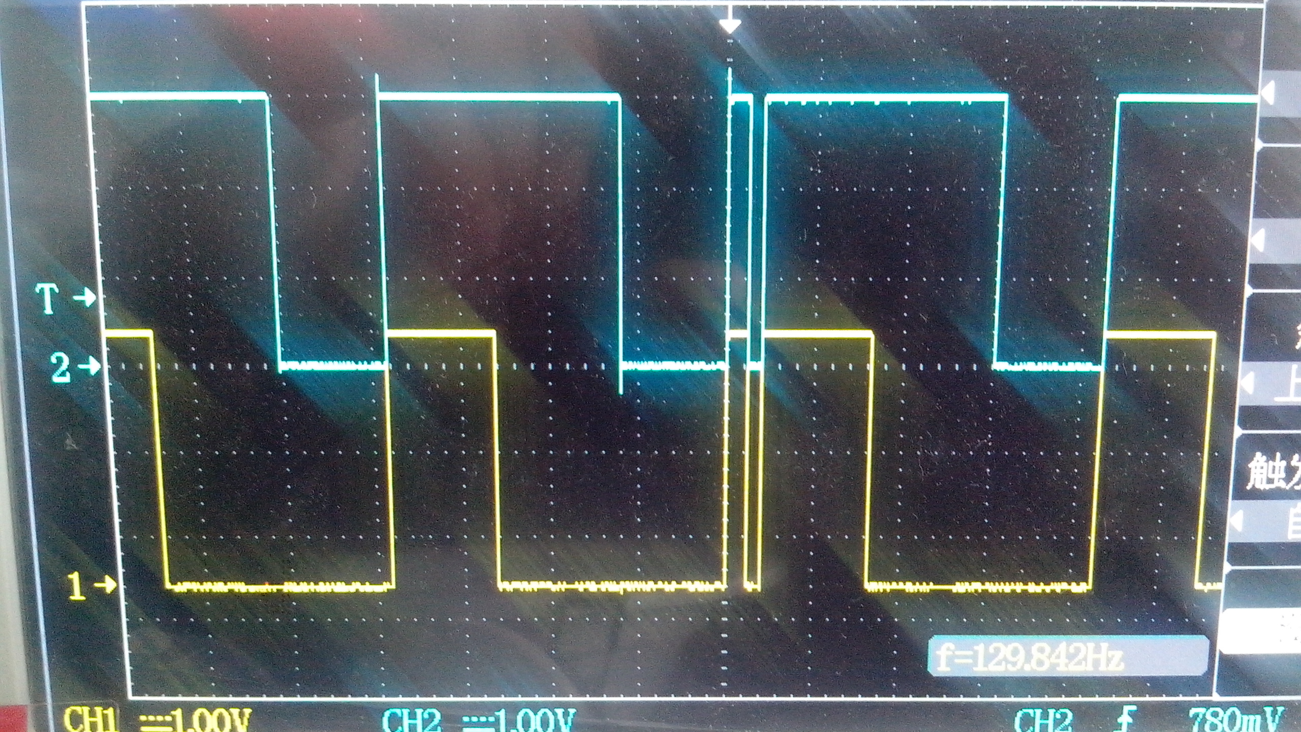
TIMER2_IRQHandler is just like the TIMER1_IRQHandler except it is handling the blue and white,but some times the pwm signals are disturbed by some reason,picture followed:
