This post is older than 2 years and might not be relevant anymore
More Info: Consider searching for newer posts

J2 debug connector on nRF51-Dongle

Hello--

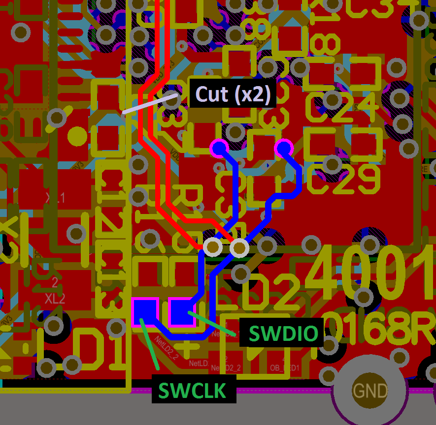
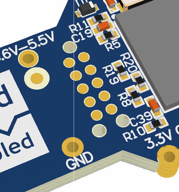
The nRF51-Dongle has these 20 pads which I think correspond to a debug port:

image description

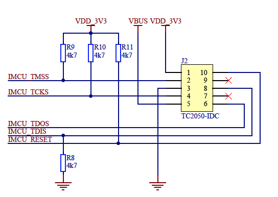
On the schematic, it looks like these feed into JTAG signals:

image description

My question is: can I solder a connector onto these pins and use the dongle as a "debug out" product (similar to the nRF51-DK) for the purposes of debugging/flashing a custom nRF51 board, or are these pins used for some other purpose?

  • That is connected to the input JTAG for programming the U3 (the Atmel processor that is doing the USB-to-JTAG). So connecting to that port will not allow you to program a custom NRF51 board.

    If you want to get a debug out capability, you'd have to disconnect U1 from SWDIO and SWCLK (remove U1 or cut the traces) and solder wires to those traces.

    If I were going to make that modification, I would cut the traces somewhere top side and solder the wires to SWDIO and SWCLK at the pads for R6 and R7 respectively. Then I'd grab GND from somewhere convenient.

    image description

    Not an easy job but definitely do-able.

    edit: Had the wrong resistors - I was confused by the silk on the top layer when the components are bottom layer.

Related