

An automatic radio test was developed based on Enhanced Shockburst (ESB), which works for all the nRF Series Chips including, nRF24LE1, nRF24LU1P, nRF51x22, as well as nRF52832. Source code is available as attached.
##What's it for?##
The Purposes of writing this code are:
- Allows R&D engineers to evaluate whether the radio of the device under development works properly in PHY layer- Evaluation mode
- Allows QA engineers to perform PCBA level radio test on predefined channels automatically -Production mode
How it works?##
-
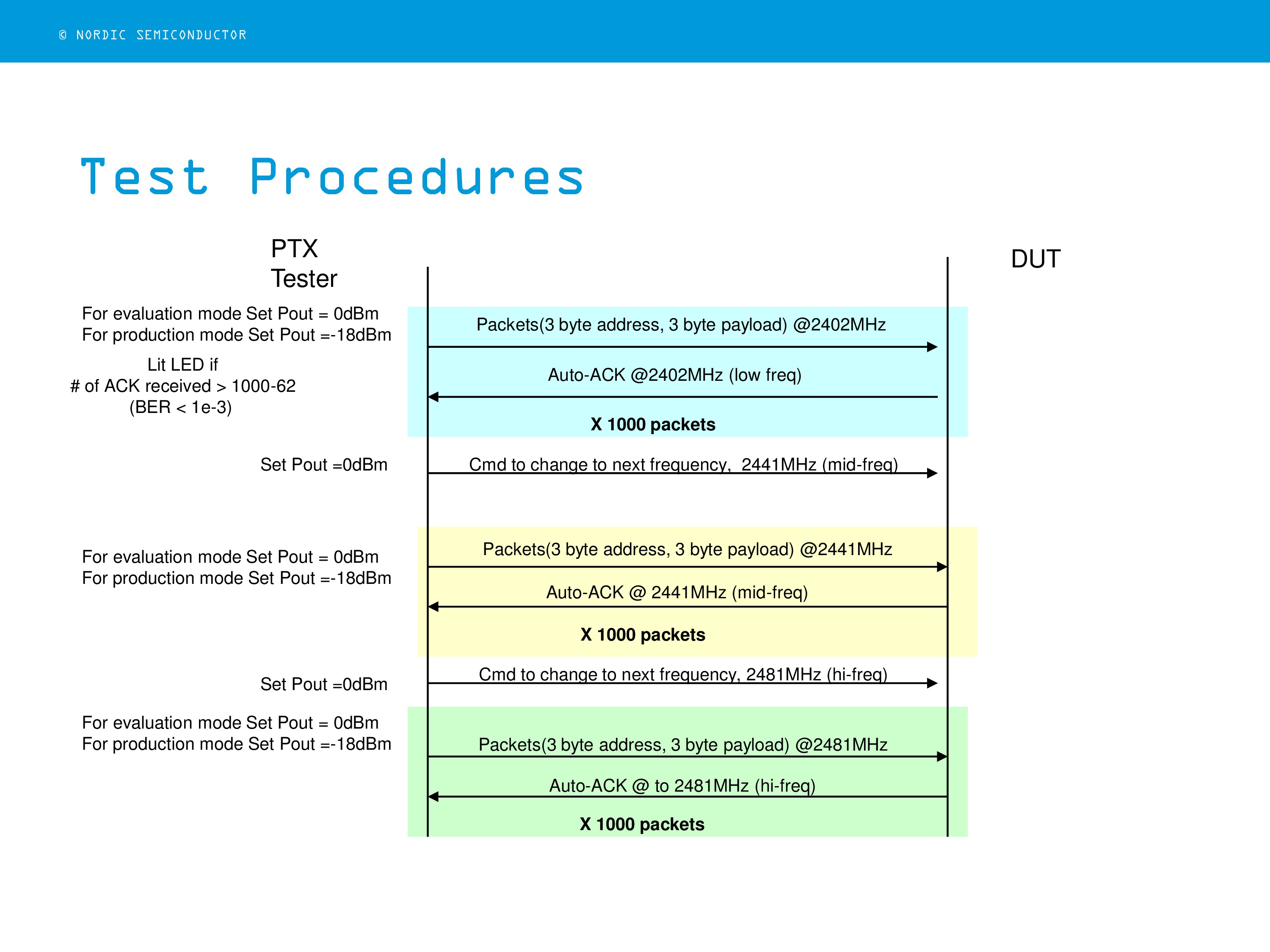
Test the radio link quality more than one frequency points automatically by sending 1000 ESB packets from the tester to the device under test (DUT).
-
With ESB, the DUT only sends out ACK to the tester when it receives the correct packets without CRC error.
-
By counting the number of ACK received, the tester can determine whether the RF link on a particular frequency points meet the pre-defined PER (packet error ratio) requirement and notify the user thru its MMI (e.g. lights a LED).
-
Three frequency points are tested. Testing finished within 5 sec.
-
Test Results shown on the Tester side. No need to wire out from DUT
-
Small firmware footprint on the DUT (PRX) side
Program size (bytes) built with Keil uvision 5: Code =3780, RO-data =224, RW-data =152, ZI-data = 2864
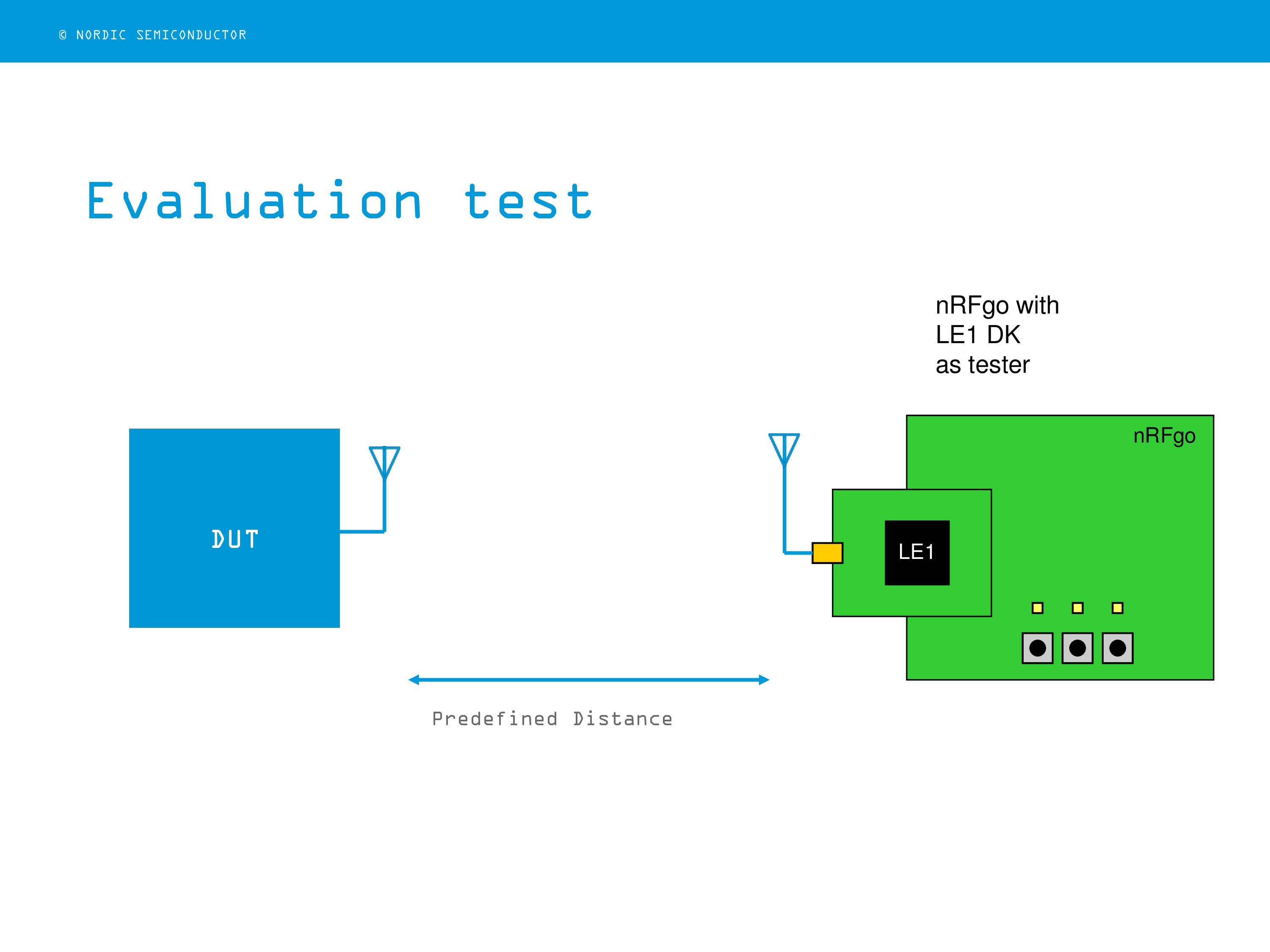
Evaluation Test Setup##
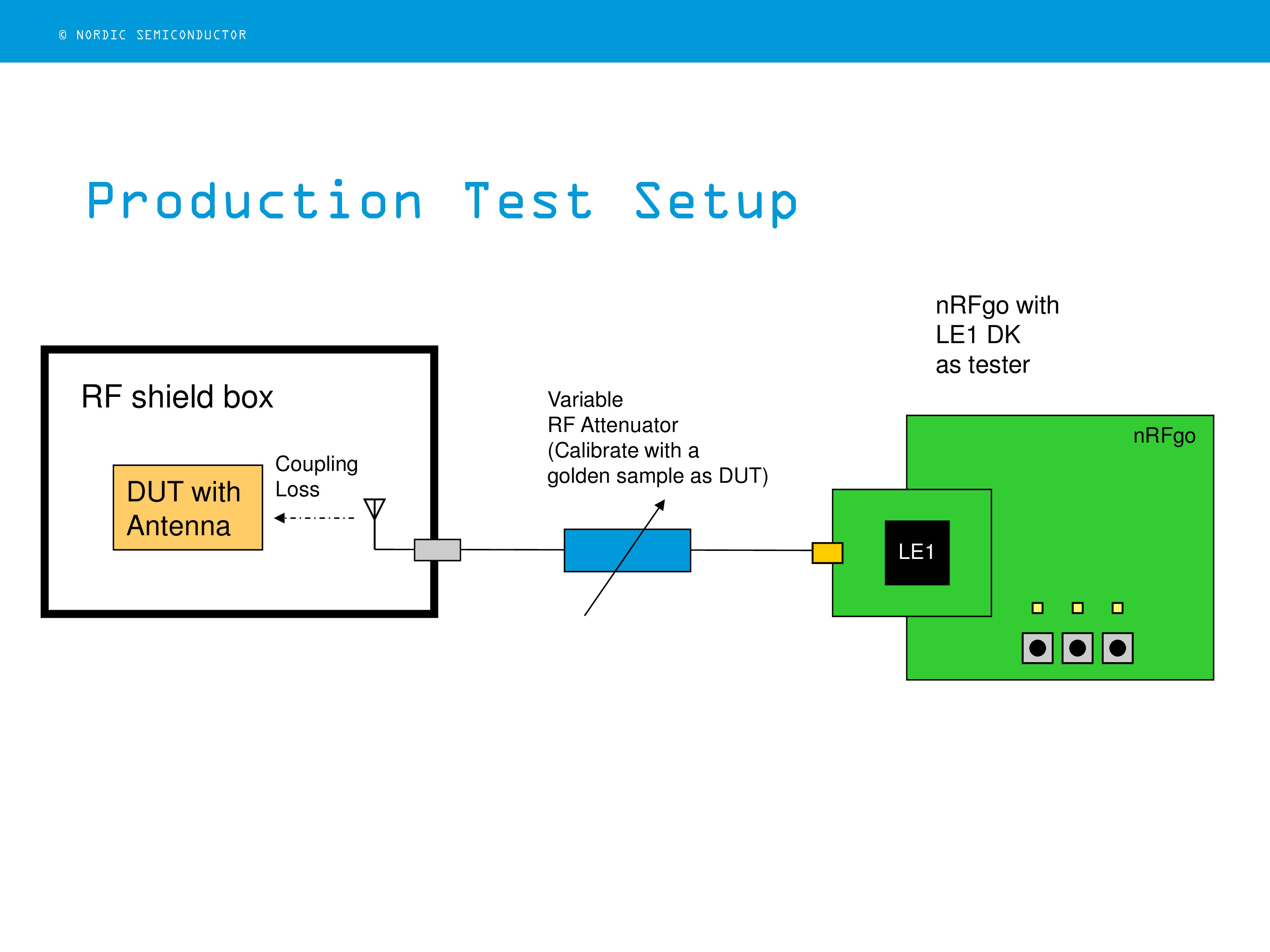
Production Test Setup
Testing Procedures
- Setup the test as shown by the above figures (either evaluation or production test).
- Download Tester code to a Nordic development board (for instance, ‘PER_LE1_test.hex’ to the LE1-DK plus nRFgo board).
- Install PER DUT test code into the PCBA under test.
- When turn on the tester, you will see a LED is blinking (e.g. LED4 for LE1-DK plus nRFgo board).
- Start the test by pressing the START button (e.g. button 0 for LE1-DK plus nRFgo board)
- Three LEDs are used to indicate whether the corresponding frequency point has passed the test. (e.g. for LE1-DK plus nRFgo board, LED0 = low channel ok, LED1 = mid channel ok, LED2 = high channel ok).
- All the 3 LEDs will glow if all channels pass the test.
- If none of the channel pass the test, the three LEDs will blink.
- Press STOP button (e.g. button 1 for LE1-DK plus nRFgo board) to stop the test. Repeat Step 5 for next test.
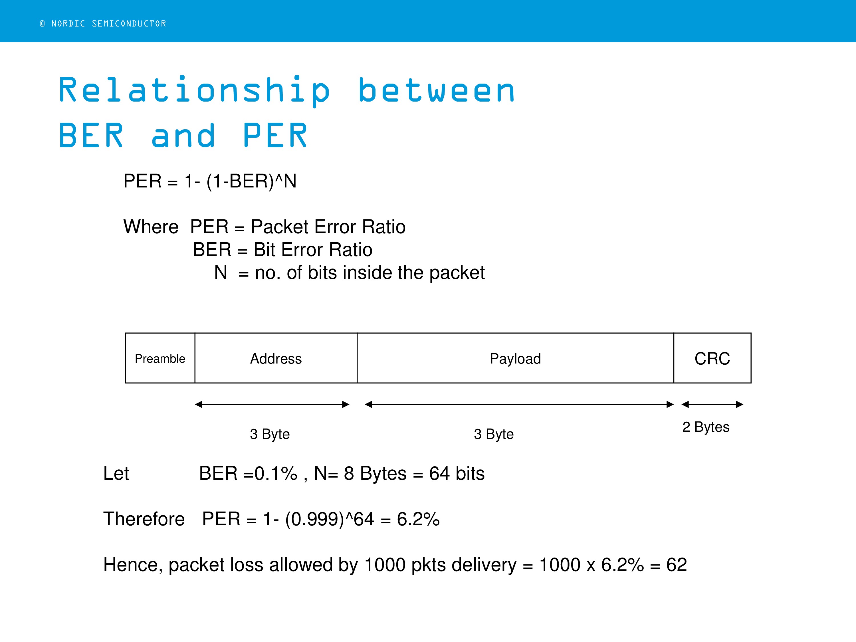
Relationship between BER and PER
As mentioned before, the RF link quality is determined by PER on the DUT. The production test setup can be used to evaluate the sensitivity of the DUT receiver based on bit error radio (i.e. sensitivity of the DUT receiver = ?? dBm with 0.1%). Following figure shows the relationship between PER and BER:
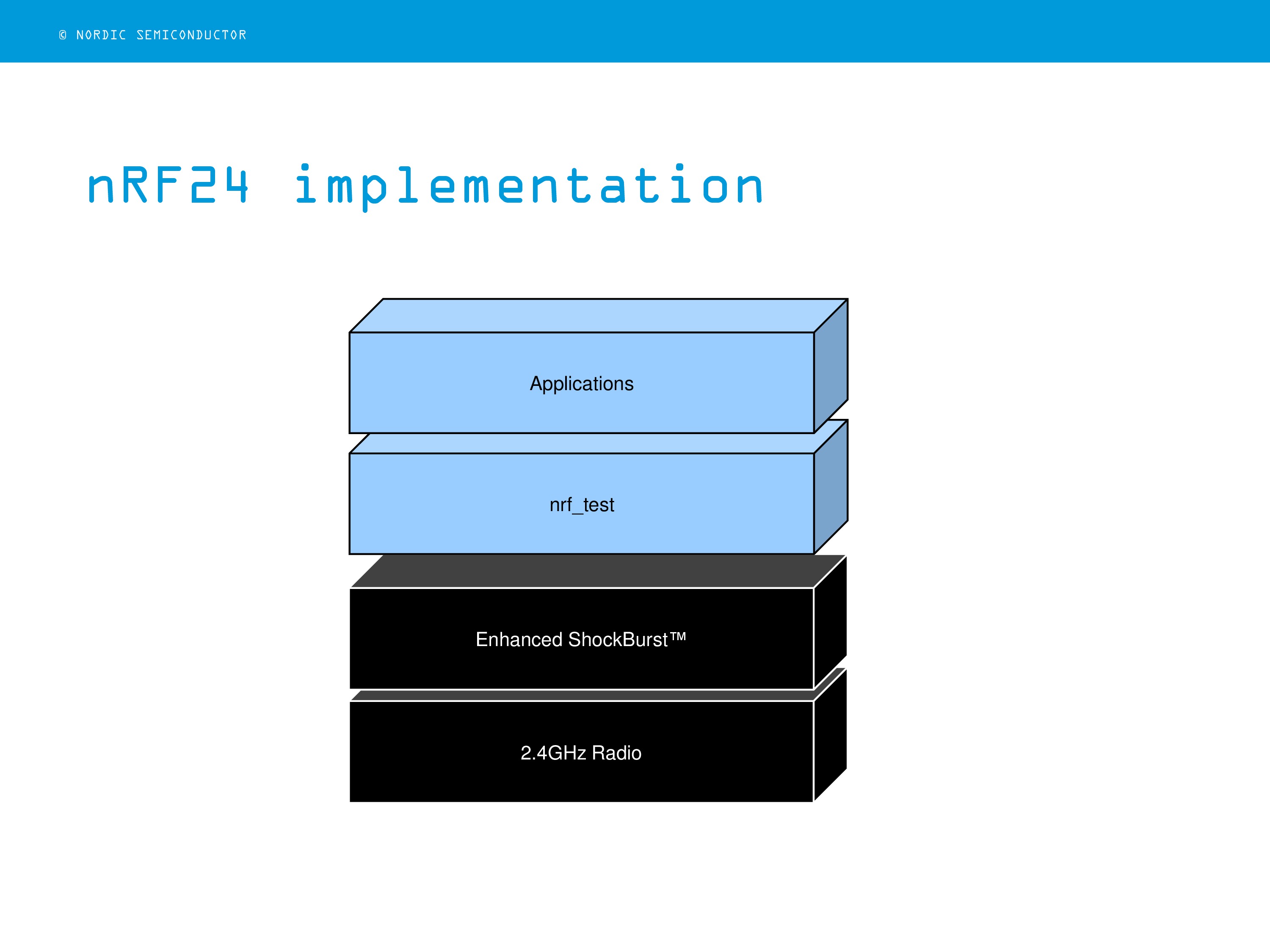
##nRF24 Implementations##
For nRF24 series ICs, ESB is built-in their radio cores. What needs to do is build a tester libs (nrf_test.c/h) for both the Tester and DUT :
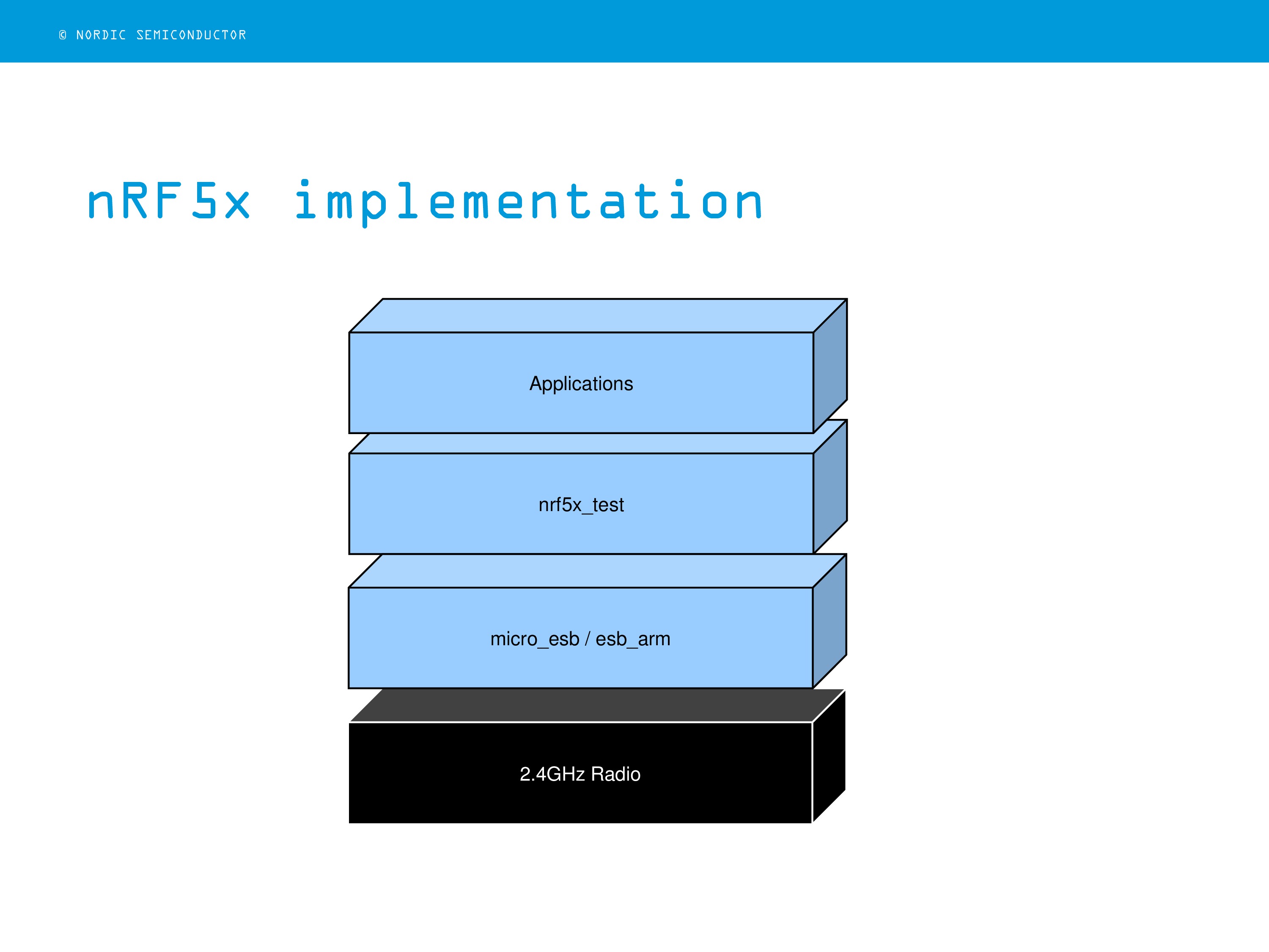
nRF5x Implementations##
For nRF5x series ICs, there are no build-in ESBs. Either using ESB libs provided by nRF5x SDK or Micro-ESB that available on Nordic devzone (keywords: micro-esb) or github for the enchanced shockburst functions :
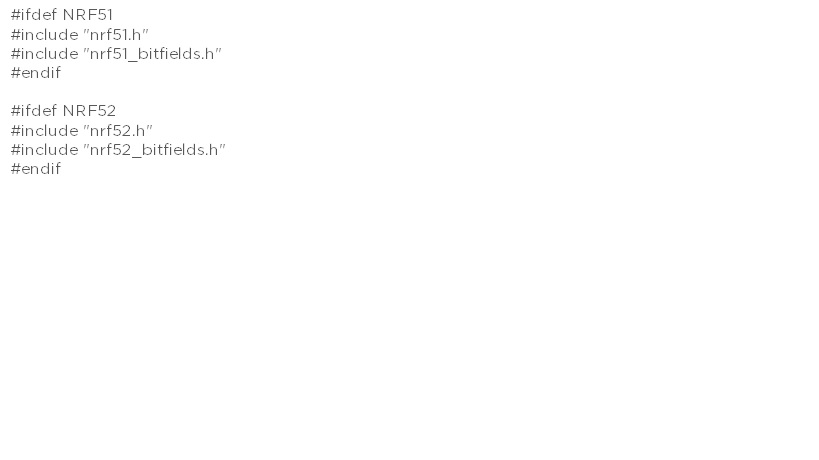
##Porting mico-ESB libs from nRF51 to nRF52 SDK It is very simple to port the existing nRF51 micro-ESB code to nRF52, or making a common library for both platforms. All we need to do is modifying the header file as below and define either "nRF51" or "nRF52" in the compiler setting accordingly:
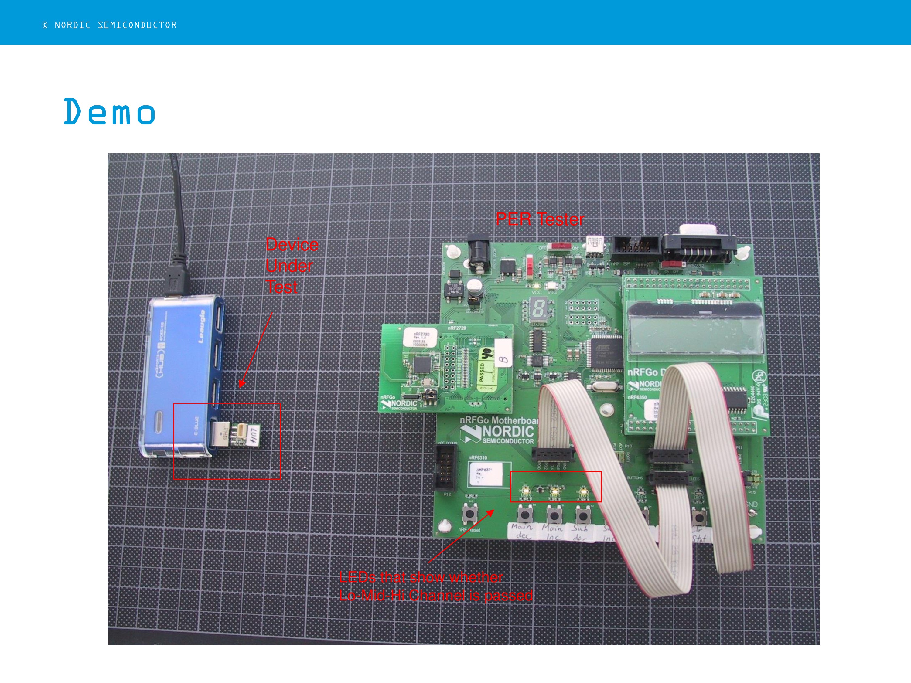
Demo
A simple demo using nRFgo mother board with nRF24LE1 DK as a tester and nRF24LU1P dongle as the DUT was carried out. LEDs on the tester are used to indicate the test results on three different radio channels (i.e. 2402, 2441, and 2481MHz) :

-

sreepriya12
-
Cancel
-
Vote Up
0
Vote Down
-
-
Sign in to reply
-
More
-
Cancel
Comment-

sreepriya12
-
Cancel
-
Vote Up
0
Vote Down
-
-
Sign in to reply
-
More
-
Cancel
Children