

Introduction:
This is a guide for the uninitiated, which I am most qualified to write. These tips cover the items I wish I had understood when I got my evaluation kits. Nordic support covered these items but I thought it might be helpful as one newby to another to publish my notes on how I got these kits up and running.
Hardware Setup:
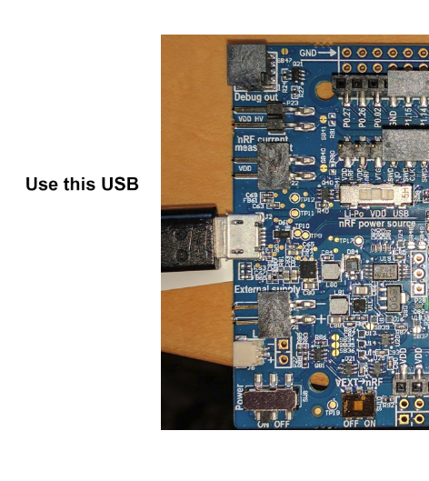
You will need two of the nRF52840 Preview DK boards and download and install both the nRF5-SDK-zip and the nRF-Connect-Windows. This will give you the basic tools to load this evaluation onto the boards. You may also want a “cell phone battery booster” to power one end for portable range checks. You might also note there are two USB connectors on the board. Use the one on the left side of the board. Effectively there are two power switches. The three position switch behind the USB connector should be set to mid position. The power switch on the bottom of the board should be pushed to the left.
Starting up:
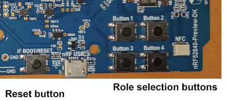
The evaluation software is loaded on both evaluation boards. Pressing buttons on the board you choose the “client” or “server” roles. In the Bluetooth world, the client is the smart end and chooses how the two boards are going to communicate. This end must be connected to a computer running terminal software. The server is configured with a button press.
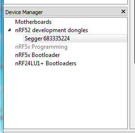
You can use nRFgo Studio to load the precompiled firmware on the evaluation boards. With the evaluation board USB connected, click on the Segger in the Device Manager window under nRF52 development dongles.
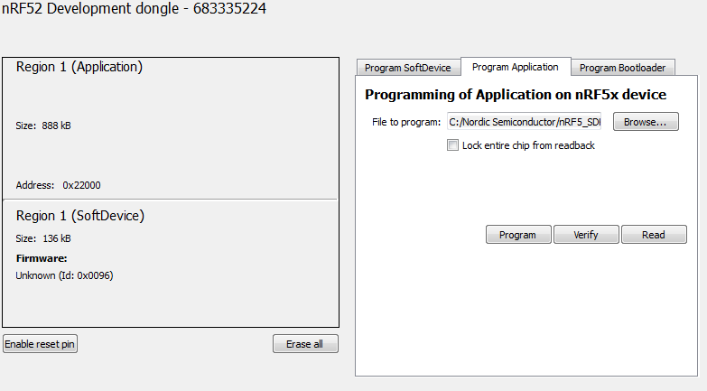
It is important to load the SoftDevice firmware that matches the application. In our case we will load the
C:/NordicSemiconductor/nRF5_SDK_13.0.0_04a0bfd/components/softdevice/s140/hex/s140_nrf52840_5.0.0-2.alpha_softdevice.hex
and the
C:/NordicSemiconductor/nRF5_SDK_13.0.0_04a0bfd/examples/ble_central_and_peripheral/experimental/ble_app_att_mtu_throughput/pca10056/s140/arm5_no_packs/_build/nrf52840_xxaa.hex.
Modules with programming tabs in the main window. I erased the device before loading the firmware modules because the SoftDevice seems to be a different size from the one shipped with the evaluation kit.
Note that these paths are based on my installation where I installed the SDK's under the NordicSemiconductor subdirectory off of my C drive root.
The power LED should be on. If you have succeeded in loading the firmware, pressing the reset button followed by button 4 will turn LED 1 on.
Setting up the terminal:
Using the free TeraTerm choose the JLink option under the Serial radio button.

The set the serial port to 115200 baud from the Serial port: option under Setup:
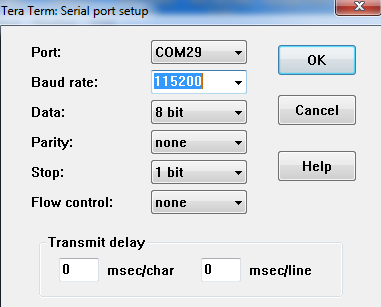
This will allow you to communicate with the “client” board. Following the screen instructions, press button 3. The board should respond with another menu.
In the menus:
On the client side, choosing 2 to adjust the parameters will bring up a menu of communication options. For the new long range tests use “Select the preferred PHY.” And choose “Coded”. That is the long range mode for BlueTooth 5. You will not need to adjust the server end as the BlueTooth client controls the PHY mode during link setup.
Good Luck:
You now have everything I know to conduct BlueTooth 5 experiments on the Nordic evaluation kits. I found a “cell phone battery booster” for server power quite useful for range tests. When you run the tests the server end LED 3 blinks with each successful transfer giving you a remote indication of throughput vs. range. Additional indications are LED 1 indicates waiting for link to be initiated and LED 2 indicates link in progress.
