

Introduction
The recently released nRF5 SDK for Bluetooth Mesh does not provide Keil project files for its example projects. Fortunately, it's relatively easy to set up your own project from scratch. This guide will show you how.
While the list of steps below might seem overwhelming, most of the settings used here, such as the linker settings and defines, can be copied from the Segger Embedded Studio project provided with the mesh SDK. The SES project can be used as a template for which files to include and which settings to use when creating Keil projects for other mesh applications.
Note that this guide creates a project for use with nRF52832-based boards. If you want to use nRF51, you will have to adjust the settings accordingly.
In this guide, we will create a project file for the light controller client application, but the same steps can be used for any example. Let's get started!
Requirements
- The most recent release of the nRF5 SDK for Bluetooth Mesh, available from the Nordic Semiconductor website. This guide currently supports version 0.10.0.
- Keil µVision 5 (note that the free version will not work due to the code size limit)
- An nRF52832-based devkit, such as the PCA10040
Creating the project
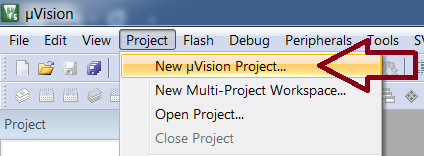
- Start the µVision IDE and close any project you might have open from before. Then create the new project by selecting "Project" -> "New project..." from the menu.
- Choose a suitable name and location for the project. A good location could be a directory adjacent to the Mesh SDK's directory, as this would make it easier to include the SDK files in the project.
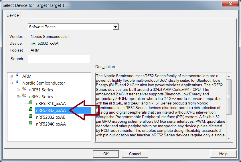
- Select the correct device from the list.
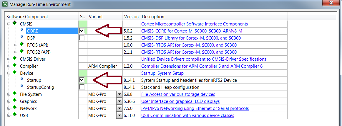
- Include support for CMSIS and the device startup files from the next dialogue. Files from these packages will be automatically supported in your project.
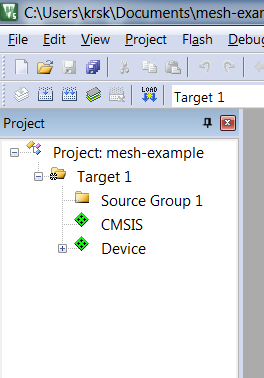
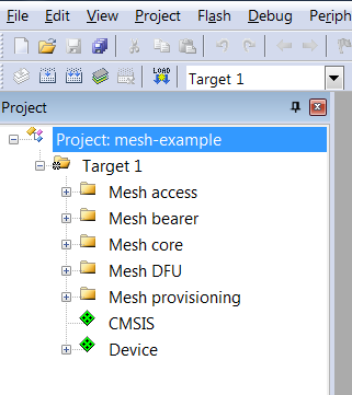
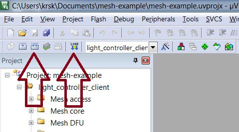
- After clicking "Ok" in the previous step, you should have an empty project that looks something like the following:
- Add the mesh SDK files to your project. To do this, create some new source groups for the files in Keil, and then add the files from the following directories in the
mesh/folder in the SDK directory:access/src,bearer/src,core/src,dfu/src,prov/src. Do not add the files from theserialfolder, as these are not used by this example. In the end, your project should look something like this:
- Add the model files by adding the source files from
models/config/src,models/health/srcandmodels/simple_on_off/src/simple_onoff_client.c. - Add the library dependencies, by adding the source files from
external/rtt/srcandexternal/micro-ecc/uECC.cto the project. - Add the example HAL files to the project, by adding the files from
examples/hal/srcandexamples/nrf_mesh_sdk.c. - Now we can finally add the application source files! Add the source files found in
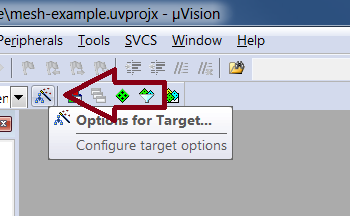
examples/light_switch/client/srcto the project. - At this point, we need to change the project settings, to make sure that linker settings are set correctly and that the necessary preprocessor include paths are added. If this is not done correctly, the project will fail to compile or run. Open the project settings by clicking the magic wand button on the toolbar.
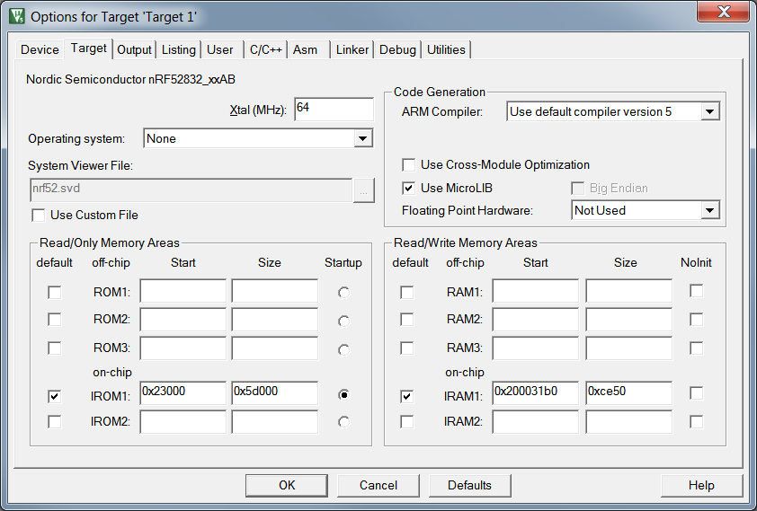
- In the first page of the project settings dialogue, set the Xtal frequency to 64 MHz, tick the box for "Use MicroLib" and set "Floating point hardware" to "Not used" (the examples do not use the FPU). Set IROM1 start to 0x23000 and size to 0x5d000. Set IRAM1 start to 0x200031b0 and size to 0xce50. The ROM and RAM settings have been customized for the S132 SoftDevice version 5.0.0, included in the mesh SDK in the
external/softdevicedirectory.
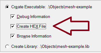
- In the "Output" tab, check the "Create Hex File" so you can use
nrfjprogto program your device later:
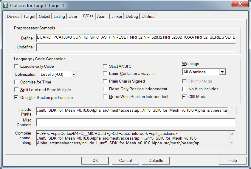
- In the C/C++ tab, add the following defines to the list of preprocessor symbols:
BOARD_PCA10040 CONFIG_GPIO_AS_PINRESET NRF52 NRF52832 NRF52832_XXAA NRF52_SERIES SD_BLE_API_VERSION=5 S132 SOFTDEVICE_PRESENT __HEAP_SIZE=1024 __STACK_SIZE=4096 - In the C/C++ tab, add the following include folders. Make sure that you change the paths as required, depending on where your project is located relative to the mesh sources!
- ..\mesh-btle\mesh\access\api
- ..\mesh-btle\mesh\access\include
- ..\mesh-btle\mesh\bearer\api
- ..\mesh-btle\mesh\bearer\include
- ..\mesh-btle\mesh\core\api
- ..\mesh-btle\mesh\core\include
- ..\mesh-btle\mesh\dfu\api
- ..\mesh-btle\mesh\dfu\include
- ..\mesh-btle\mesh\prov\api
- ..\mesh-btle\mesh\prov\include
- ..\mesh-btle\models\config\include
- ..\mesh-btle\models\health\include
- ..\mesh-btle\models\simple_on_off\include
- ..\mesh-btle\examples
- ..\mesh-btle\examples\light_switch\include
- ..\mesh-btle\examples\light_switch\client\include
- ..\mesh-btle\examples\hal\include
- ..\mesh-btle\external\micro-ecc
- ..\mesh-btle\external\rtt\include
- ..\mesh-btle\external\softdevice\s132_5.0.0\s132_nrf52_5.0.0_API\include
- ..\mesh-btle\external\nRF5_SDK_14.0.0_3bcc1f7\components\boards
- ..\mesh-btle\external\nRF5_SDK_14.0.0_3bcc1f7\components\drivers_nrf\hal
- ..\mesh-btle\external\nRF5_SDK_14.0.0_3bcc1f7\components\drivers_nrf\delay
- Set optimization settings based on your requirements. In the end, the C/C++ tab should look something like this:
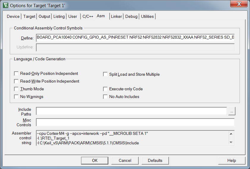
- Copy the defines from the C/C++ tab into the "Defines" section of the Asm tab:
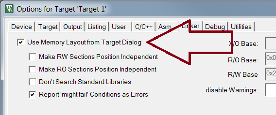
- In the linker tab, verify that the "Use Memory Layout from Target Dialog" checkbox is checked.
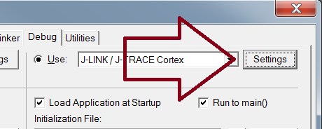
- Next, go to the Debug tab. Select "JLink/J-Trace Cortex" as the debugger/programmer.
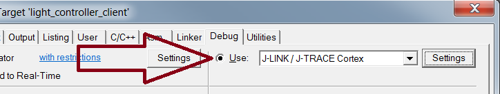
- Click "Settings" to open the debugger settings dialogue.
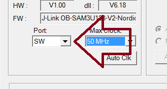
- In the debugger settings, make sure you select SW instead of JTAG in the "Port" field.
- Now, compile and run!
At this point you should have a working Light controller client. If you open the J-Link RTT Viewer, you should be able to see some logging output from the application.
Troubleshooting steps:
If something goes wrong, check the following points:
- Completely erase the device before programming the application
- Check that you remembered to program the SoftDevice to the chip before flashing the example


