

Hello all, this tutorial goes to a fellow named Emil who helped me with this project.
Number 1_ Make sure you set up the terminal viewer For debugging with real.You need it to see the values coming outta your ADXL 345 chip in the case you don't have an osciliscope or a Logical unit. Click here
Number 2_ How does the ADXL 345 work? ADXL 345 datasheet says there are two ways you could read x, y and z information from the register. 1 I call it serial mode in which you send (0x80| 0x40 | 0x31) to the ADXL345's address 31 register and get a serial output from register's 32 (LSB of x axis), 33 (MSB of x axis), 34 (LSB of Y axis), 35 (MSB of Y axis), 36 (LSB of Z axis) and 37 (MSB of Z axis).
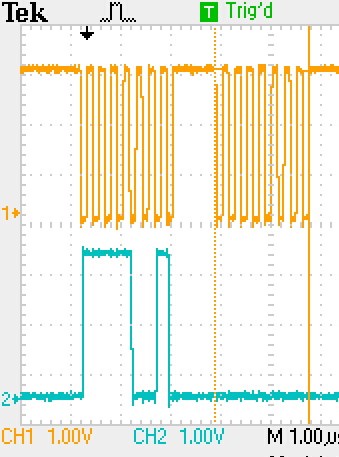
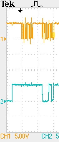
MY RECOMMENDATION IS NOT TO USE THIS MODE IF YOU ARE USING PCA 1008 since the TX and RX buffer are two bytes only so the rest of the data send back from the serial mode will be lost as your TX and RX buffers get empty and full. Mode 2 of operation is like this :) Basically you send in one byte of ((the read command)=0x80 | the address of the register you are interested in= let's say 32 which is for x LSB) + one byte of dummy data like 0x00, and get back two bytes from the accelerometer. ATTENTION (THE FIRST BYTE RECEIVED SHOULD BE IGNORED AND THE SECOND ONE SHOULD BE USED). but why? SPI communication has one dedicated line (MOSI/ Master Out Slave In) for sending commands and a dedicated line for receiving informations from slave (MISO/ Master in Slave out); thus, while the master (nRF chip or a microelectronic) sends information it simotanesly receives information too. But what information is it receiving ? JUNK . Therfore we ignore the first byte received from the slave. Now, one might ask why do we send a dummy byte to the slave? Well, of you red the SPI communication you see that in order for any communcation to happen we need to activate the clock shared between the master and slave and by sending a dummy byte we make sure that the clock is active so that the slave could send the master its information. The one on left is the MOSI signal and the one on right is the mosi. Sorry its a bit missy its just for you to get a general idea. Do not compare the to pictures literally.
Now that you know these lets get to the coding. First, Take a look at this from Spark Fun as the code they have (not the advanced) for the arduino gives you an idea of how stuff work in general. Do not try to get everything at once as it needs time to soak in to mind :) so good luck.
When it come to ADXL 345 codding you should configure the SPI_MASTER_INIT_DEFAULT like this:
          switch (spi_master_instance)
            {

                case SPI_MASTER_0:
                {
        					 spi_master_config_t spi_config0 = SPI_MASTER_INIT_DEFAULT;

                    spi_config0.SPI_Pin_SCK  = 4;
                    spi_config0.SPI_Pin_MISO = 3;
                    spi_config0.SPI_Pin_MOSI = 2;
                    spi_config0.SPI_Pin_SS   = pinnum;
        					 spi_config0.SPI_CONFIG_ORDER = (lsb ? SPI_CONFIG_ORDER_LsbFirst : SPI_CONFIG_ORDER_MsbFirst);

            err_code = spi_master_open(spi_master_instance, &spi_config0);
            APP_ERROR_CHECK(err_code);

                }
                break;

        ..........


            static inline uint8_t* Adxl362_SpiTransfer(uint8_t * const txBuffer, const uint16_t txBufferLength,
            	uint8_t * const rxBuffer, const uint16_t rxBufferLength, uint8_t sub)
            {
            	while (_isTransferring)
            	nrf_delay_ms(1);

            	uint32_t result = spi_master_send_recv(SPI_MASTER_0, txBuffer, txBufferLength, rxBuffer, rxBufferLength);
            	APP_ERROR_CHECK(result);

            	nrf_delay_ms(1);
            	return &_rec[sub];
            }

    .............

    void main(){

    bsp_configuration();
                  spi_master_init(SPI_MASTER_0, spi_master_0_event_handler, false,pin );
                  spi_master_send_recv(SPI_MASTER_0, Powermode_Set, 2, m_rx_data_spi, 2);
                  spi_master_send_recv(SPI_MASTER_0, Data_Format, 2, m_rx_data_spi, 2);
    for(;;){

            uint8_t num8[20]={0,0,0,0};
            _buf[0] = tx_DARA0;
            _buf[1] = 1;
            _buf[2] = tx_DARA1;
            _buf[3] = 2;
            _buf[4] = tx_DARA2;
            _buf[5] = 3;
            _buf[6] = tx_DARA3;
            _buf[7] = 4;
            _buf[8] = tx_DARA4;
            _buf[9] = 5;
            _buf[10] = tx_DARA5;
            _buf[11] = 6;


_rec[0]=0;
            _rec[1]=0;
            	_rec[2]=0;
            	_rec[3]=0;
            	_rec[4]=0;
            	_rec[5]=0;
                _rec[6]=0;
            	_rec[7]=0;
            	_rec[8]=0;
            	_rec[9]=0;
            	_rec[10]=0;
            	_rec[11]=0;


              pin=5;

              spi_master_init(SPI_MASTER_0, spi_master_0_event_handler, false,pin );

              uint8_t* x1=Adxl362_SpiTransfer(&_buf[0],2,	&_rec[0],2,1);
              uint8_t* x2=Adxl362_SpiTransfer(&_buf[2],2,	&_rec[2],2,3);
              uint8_t* y1=Adxl362_SpiTransfer(&_buf[4],2,	&_rec[4],2,5);
              uint8_t* y2=Adxl362_SpiTransfer(&_buf[6],2,	&_rec[6],2,7);
              uint8_t* z1=Adxl362_SpiTransfer(&_buf[8],2,	&_rec[8],2, 9);
              uint8_t* z2=Adxl362_SpiTransfer(&_buf[10],2,	&_rec[10],2, 11);
    }}

Good Luck All.

