

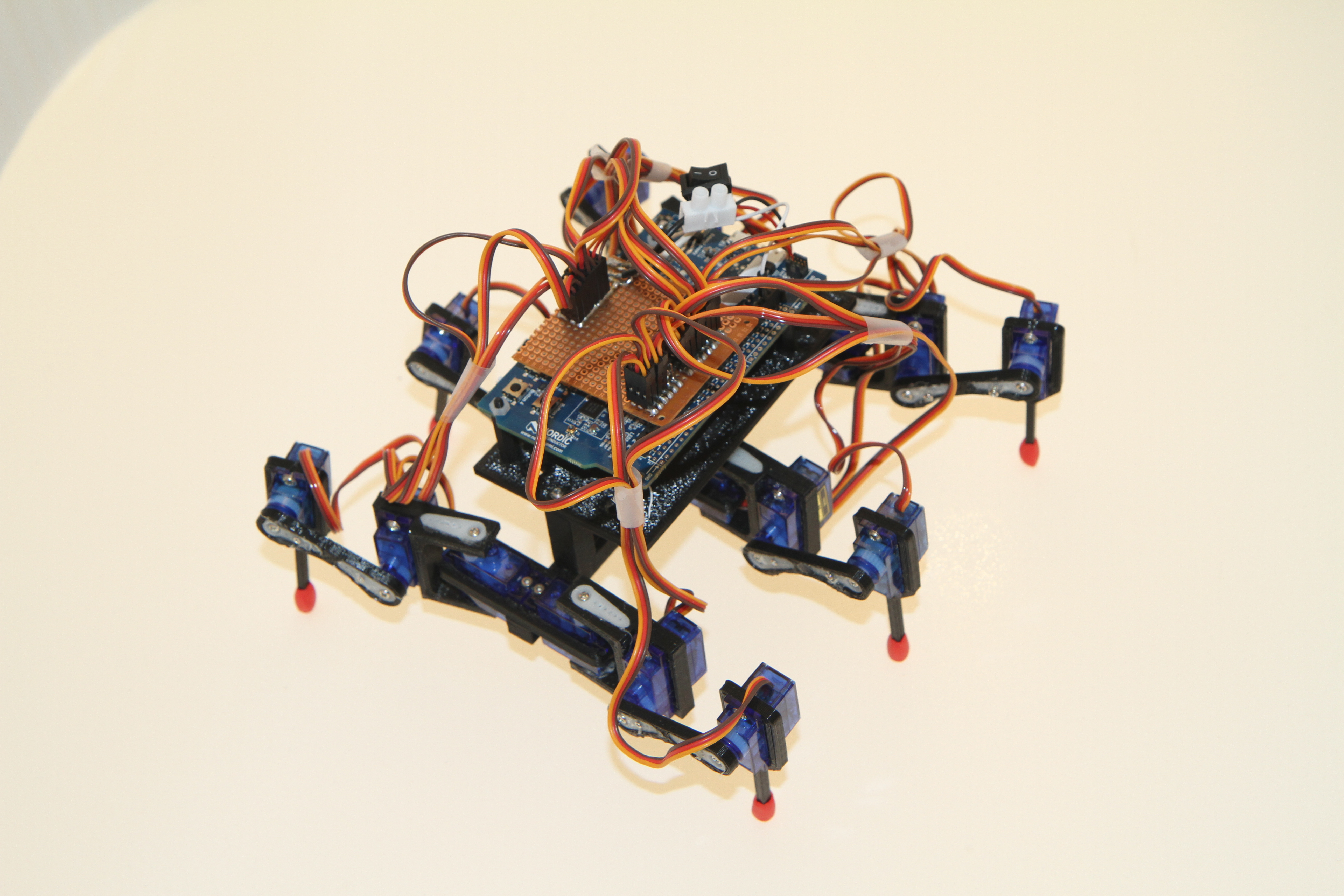
This series of posts will describe a new toy here at Nordic: The nRF Hexapod. The post will be divided in multiple parts, this part describing the project in general and the hardware that is required. All parts of this project is open source so you can make one yourself.
The hexapod is built to show the power of nRF52. Using hardware PWM we can control up to 20 servos simultaneously, 12 using the PWM peripheral and 8 using a combination of TIMER, PPI and GPIOTE. This project also shows how a single chip solution can both have a connection over BLE and do real time tasks at the same time.
Hardware
Servos
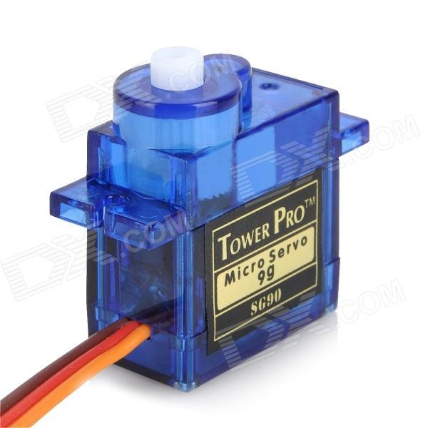
The hexapod has six legs with three servos each, a total of 18 servos. The servo used is called “SG90”, but also has a lot of other names as it is a very popular and common servo used. The servo weighs only 9 grams.
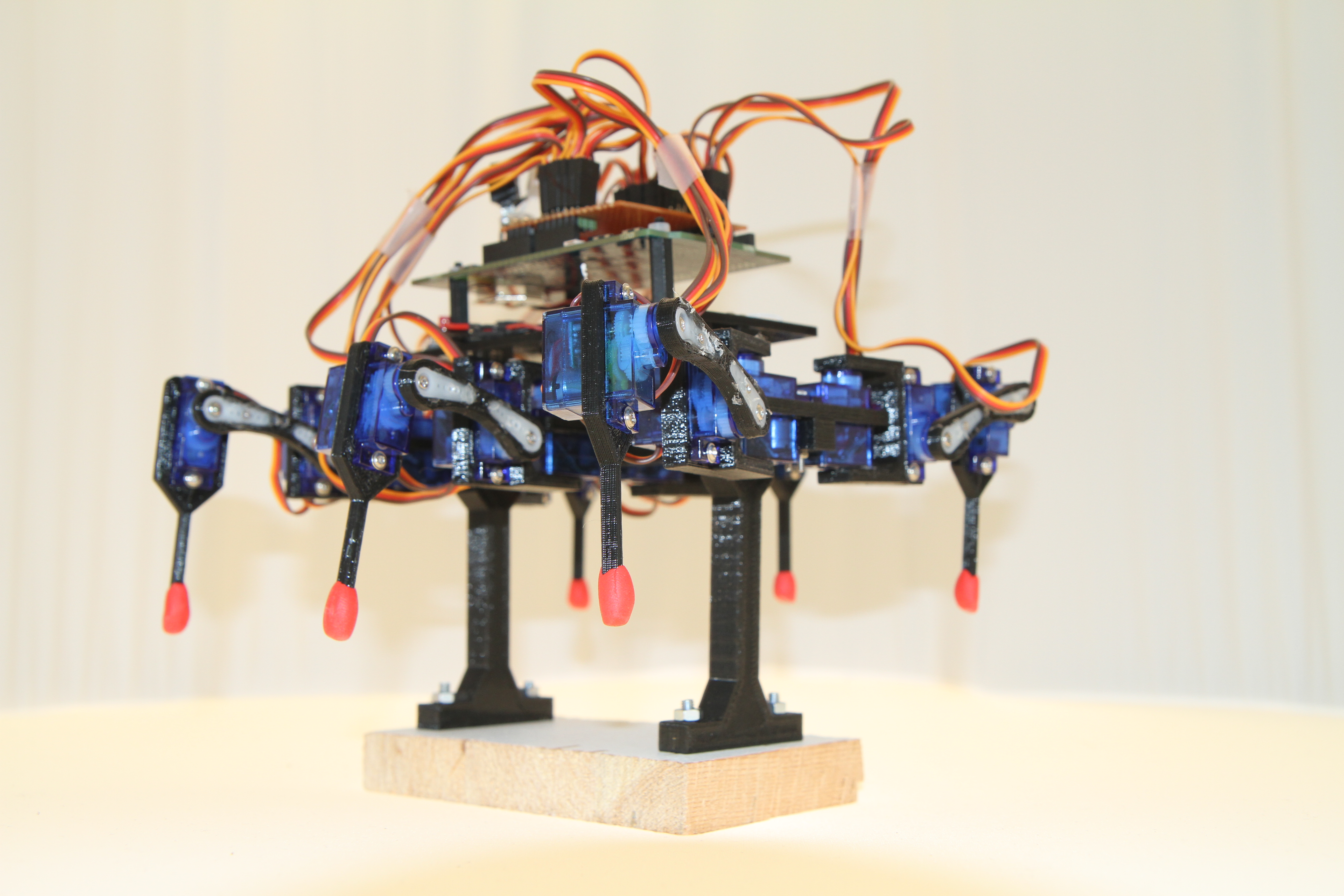
Frame
The frame is 3D printed. 3D models and more pictures can be found on Thingiverse. It is based on another 3D model, with some modifications like two more legs, longer frame and a bracket for mounting nRF52 DK. A stand was printed to test the hexapod without having to place it on the ground. It is also great for storing the hexapod when not using it.
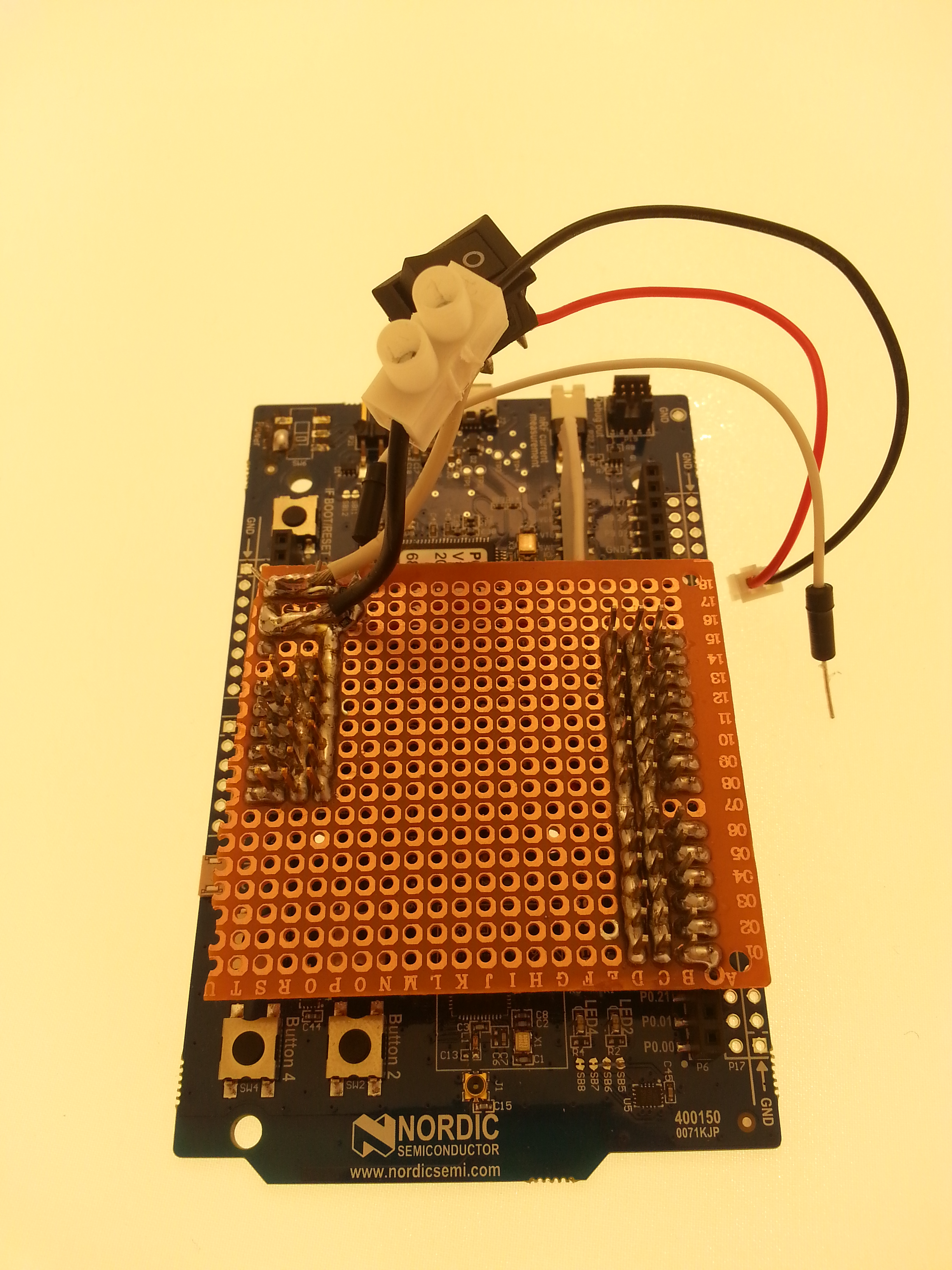
Connection board
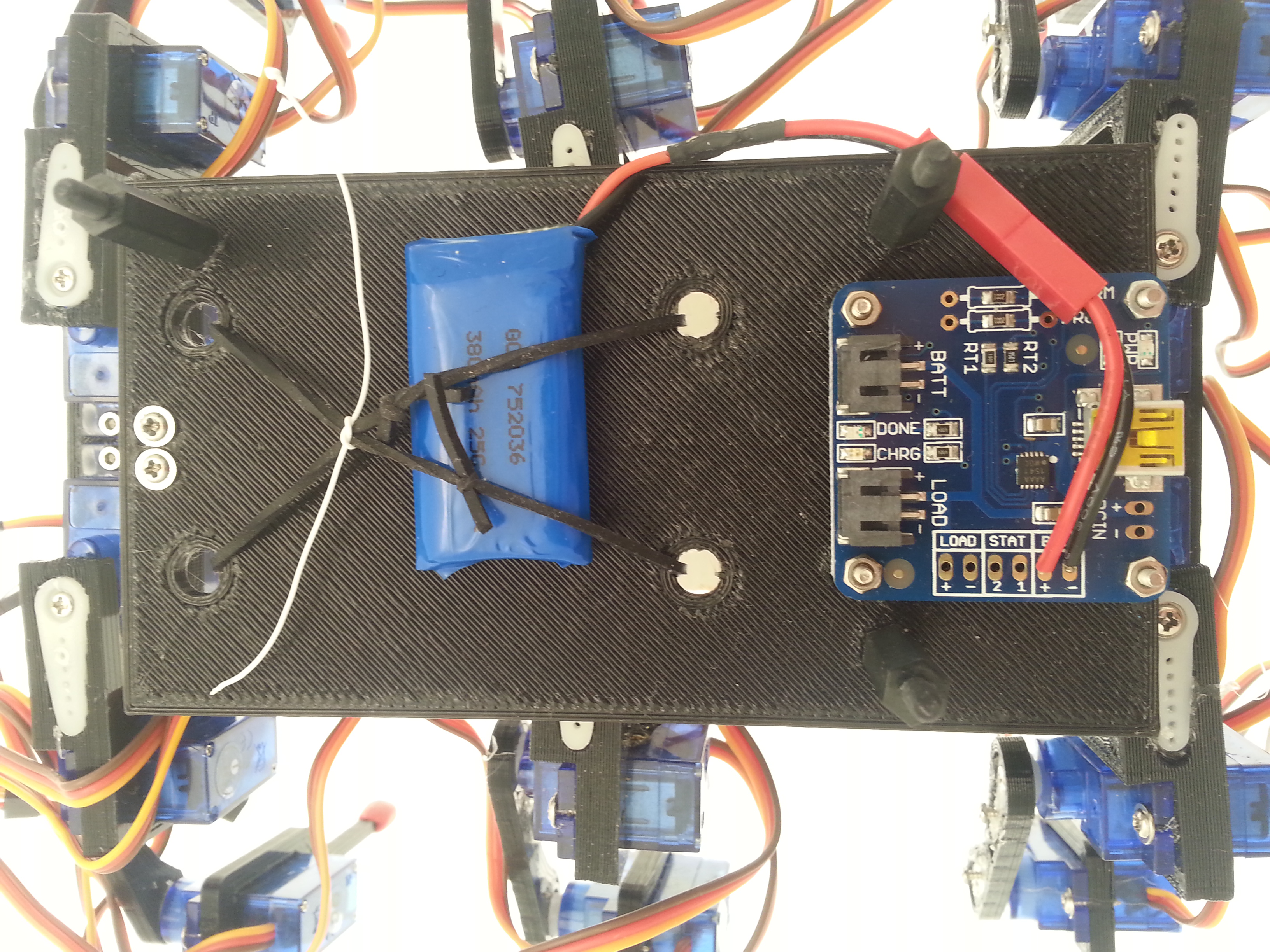
A prototype board has been soldered to be able to connect all the servos, the battery and the external voltage divider for battery measurement. An easier solution may be to use Arduino prototype shield.
Battery
The hexapod is powered from a single cell LiPo battery. Since the voltage of a single cell LiPo battery varies from 3V to 4.2V, it cannot be connected directly to the nRF52 (maximum voltage on any pin is 3.6V). The battery is therefore connected to the 5V pin on the DK. This is routed directly to the on board 3.3V regulator, see the schematic in nRF52 DK Hardware Files. The battery is also connected directly to the servo positive input since the servos can take voltages varying from 3V to 6V. Currently a 380mAh battery is used, but the plan is to switch this out for a 1200mAh battery.
5V from usb is connected to 5V rail if the power switch is in ON position. This may cause issues if both the usb cable is plugged in and the battery is connected (5V from usb is connected directly to the battery). To avoid this potential problem, the switch has been removed and the second pole of the switch is bridged (the one between the regulator and vdd on nRF52, again see the schematic). This means that the chip will always be powered as long as there is voltage on 5V pin. An external switch is used to turn on/off power (see previous picture).
The only other change that is done on the DK is that SB5 and SB6 is cut since the pins for LED1 and LED2 is used to control servos.
Battery measurement
Battery voltage measurement is done with the ADC (SAADC) on nRF52. A voltage divider is needed since the voltage of the battery is higher than Vdd. The resistor values were chosen according to this blog post about measuring lithium ion battery with nRF52.
Charging
A charging board is used to allow for charging without disconnecting the battery. The battery is charged by simply connecting a mini usb cable to the charging board. With this configuration the battery can be charged while using the hexapod.
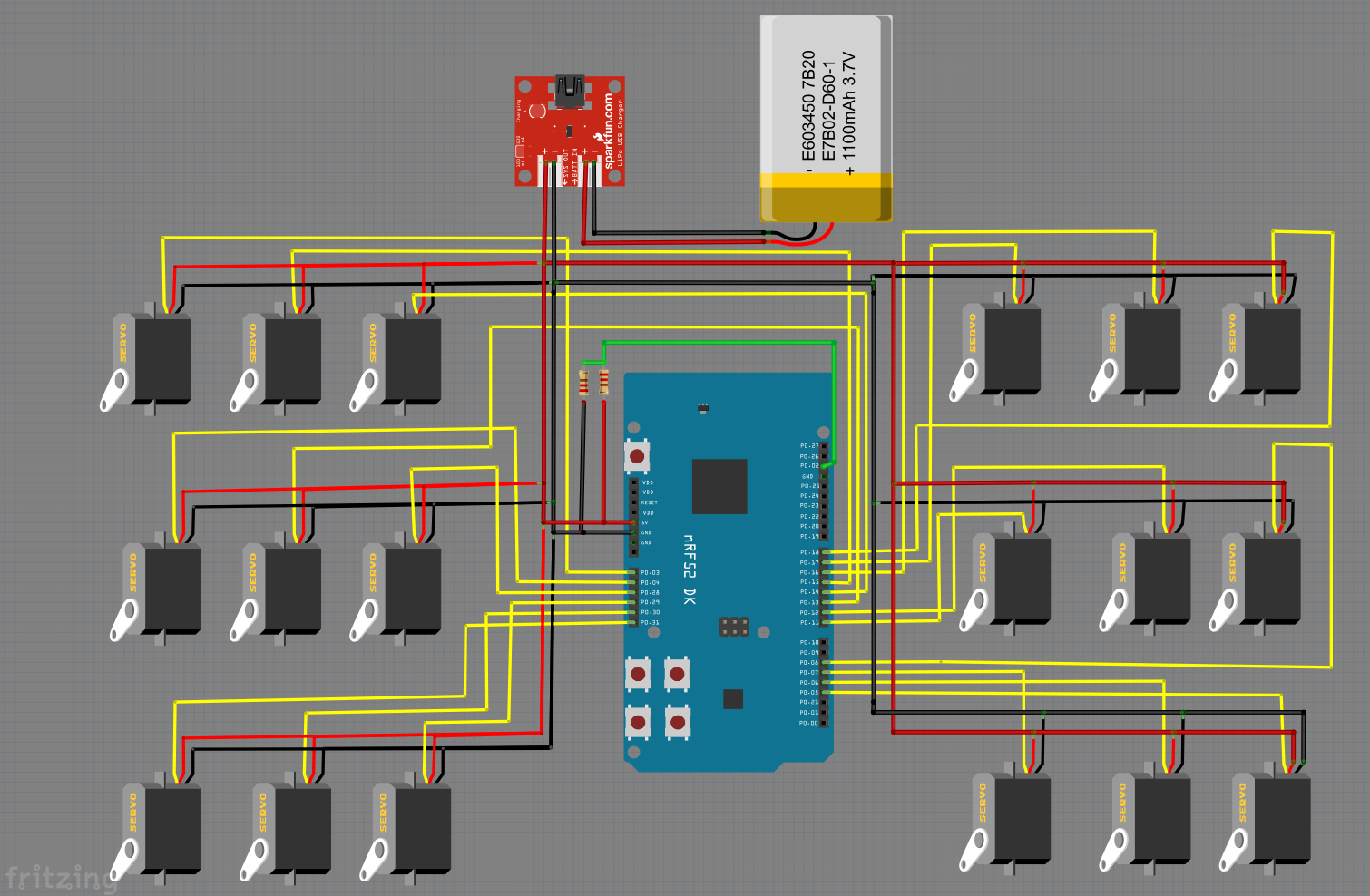
Wiring diagram
Below is a picture of the complete wiring diagram using Fritzing. The charging board is from Adafruit, but looks the same as the one from Sparkfun.

Video
Finally, a video of the hexapod walking.
New toy in the office! #Hexapod using #nRF52DK controlled with #nRFToolbox App. See it at #MakerFaire Bay Area! pic.twitter.com/uY8BkHAC5M
— Nordic Semiconductor (@NordicTweets) 11. mai 2016
For those who want to get a hold of the Software for the Hexapod, it is available here: https://github.com/OBauck/Hexapod.


