
Hi ,
1. I am using nrf52833 Soc as transmitter and nrf52833 + Core-hw antenna array(4X4) as receiver. I have set the switching pattern of antenna array as round-robin pattern (7,7,8,9,10,11,12,13,14,15,0,1,2,3,4,5,6) . During this time I have received the unstable iq samples as fig_1 in which the phase difference in the reference period was not 90 degree(unstable and high fluctuations in phase difference).
2. In the second case,I have used the same setup as above.I have changed only the antenna switching pattern to return to first pattern(7,7,8,7,9,7,10,7,11,7,12,7,13,7,14,7,15,7,0,7,1,7,2,7,3,7,4,7,5,7,6).This time Iam getting a proper signal with reference period showing a regular 90 degree phase difference as shown in fig_2.
What could be the reason for unstable phase difference in case_1 and stable phase difference in case_2 (the only change - antenna switching pattern).
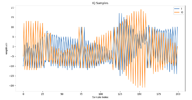
Fig_1
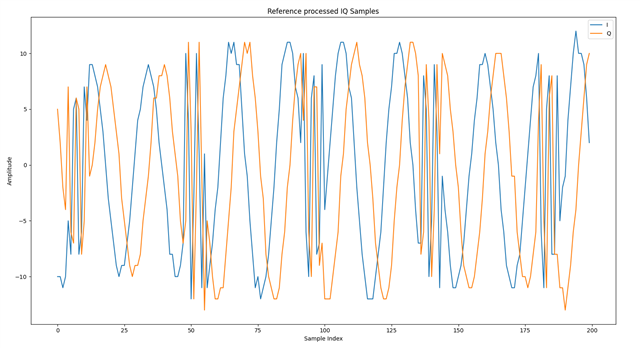
Fig_2

