
Hello all, to optimize the BOM and size of our device(Tag based on nRF51822), the external divider was replaced by software configuration to measure the battery voltage. In our design the CR2032 cell was used and connected to nRF51 directly. We have chosen a free AIN pin and configured it with next:
- SupplyOneThirdPrescaling  ADC_CONFIG_INPSEL_SupplyOneThirdPrescaling

- ADC_CONFIG_RES_10bit

- ADC_CONFIG_REFSEL_VBG
Edited: To be more precise
NRF_ADC->CONFIG = (ADC_CONFIG_RES_10bit<< ADC_CONFIG_RES_Pos)|(ADC_CONFIG_INPSEL_SupplyOneThirdPrescaling << ADC_CONFIG_INPSEL_Pos)|(ADC_CONFIG_REFSEL_VBG << ADC_CONFIG_REFSEL_Pos)|(ADC_CONFIG_PSEL_Disabled<<ADC_CONFIG_PSEL_Pos)|(ADC_CONFIG_EXTREFSEL_None<< ADC_CONFIG_EXTREFSEL_Pos);
So than I calculate supply voltage as
Vin = (ADCres*1.2V/1024)*3
If I power my device from Dev.board (2.95V) the conversion results correctly and device show 2.95V measured. However, if I power the device with cr2032 cell (not new) the voltage measured on inserted in device's slot is 2.86V but ADC conversion results with value 2,73V. So I have a few questions:
-
How stable is value of VBG?
-
Is there any circuit between the Vcc pin and divider "SupplyOneThirdPrescaling" inside of the chip?
-
What is SupplyOneThirdPrescaling divider accuracy?
Please help.
P.S. The average current consumption of device is about 200uA. The Vcc pin was measured with osciloscope, the voltage ripples are about 1-3mV.
Best regards,
Added:
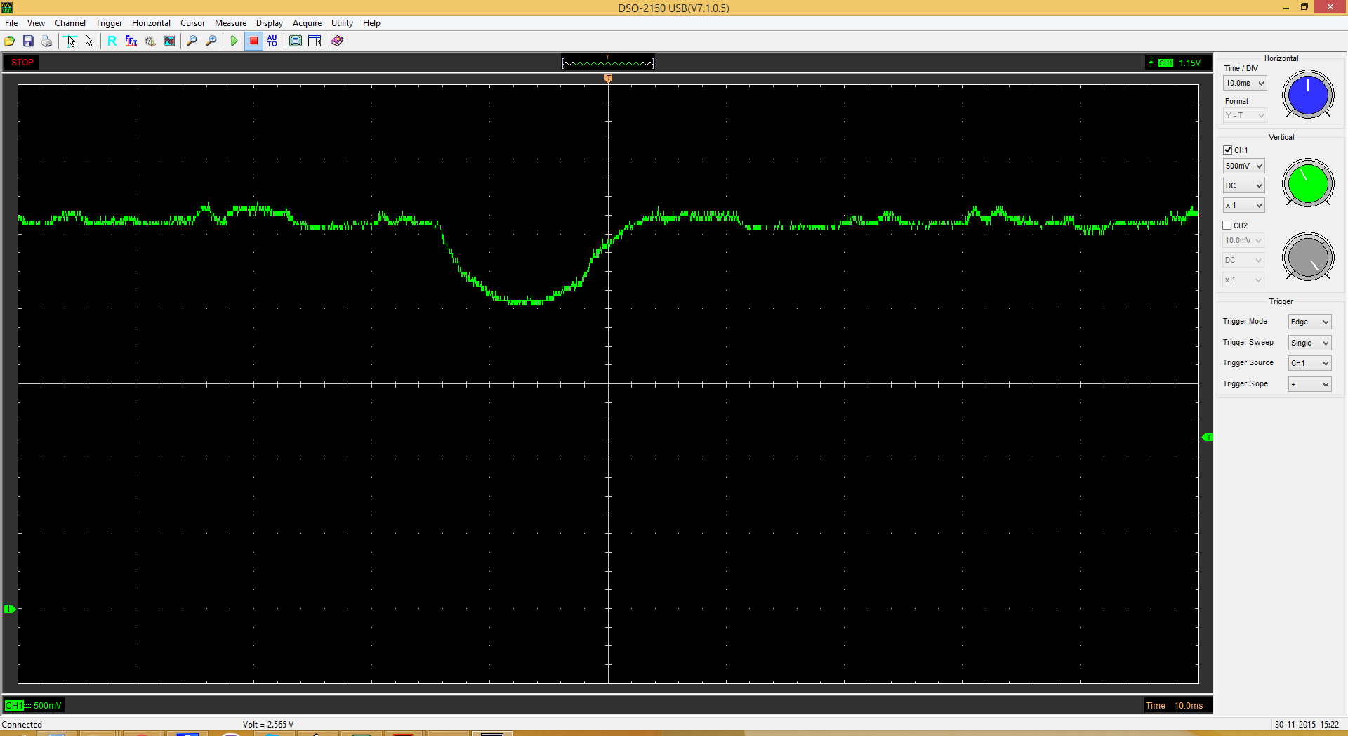 I measured battery voltage at igher time resolution and noticed a voltage kink with same period as the ADC measurement occured. It explains the measurement results (bottom part of voltage kink has the same value as measured by ADC). However, that to do next is unclear. To add huge uF cap? The PS says: "I ADC - Current drawn by ADC during conversion. - 260 μA" and it doesnt seem to be so high to make such voltage lowering.
Added: I also measured the current. Each time when ADC measurement occured the 4mA current pulse noticed. Could internal 1/3 divider cause such current flow?
