
I'm learning to use the Zephyr toolchain and in the interest of connecting the Zephyr-side coding to the i2c protocols I am familiar with, I have some questions.
I'm trying to decipher how the enums and macros that are defined in Zephyr/device.h go about acquiring the api of a device defined in the device tree.
I'll give a specific example here -- I'm playing with the example (on sdk v2.5.0) "sensor/lsm6dsl." I've got this example working on the board "xiao_ble_sense," which took a bit of configuring of the power pin (and if you'd like to reproduce THAT, here's the device tree node for that sensor).
lsm6ds3tr_c: lsm6ds3tr-c@6a {
		compatible = "st,lsm6dsl";
		reg = <0x6a>;
		irq-gpios = <&gpio0 11 GPIO_ACTIVE_HIGH>;
		status = "okay";
	};

// AND ON THE ENABLE PIN:

lsm6ds3tr-c-en {
		compatible = "regulator-fixed-sync", "regulator-fixed";
		enable-gpios = <&gpio1 8 (GPIO_OPEN_SOURCE | GPIO_PULL_UP | NRF_GPIO_DRIVE_H1)>;
		regulator-name = "LSM6DS3TR_C_EN";
		regulator-boot-on;
		startup-delay-us = <3000>;
	};
In this specific example, there is a line whose purpose and usability are simple and effective, but which does SOMETHING under the hood that I can't quite track down.
The line is
which makes perfect sense -- we are setting the sensor attribute on our device, and setting the sampling frequency to our output data rate structure, then checking for errors.
WITHIN this line, however, something strange happens. I know from working with this IMU in CircuitPython that the register that needs to get set is CTRL1_XL which is located at 0x10 on the lsm6dsl (and here's a link to that datasheet: https://www.st.com/resource/en/datasheet/lsm6dsl.pdf). The relevant page: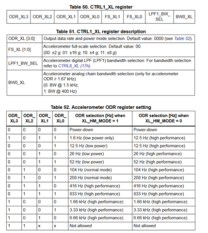
Here is where I can't find an answer in the code -- how does sensor_attr_set take the arguments:
SENSOR_CHANNEL_ACCEL_XYZ (which expands to "3")
SENSOR_ATTR_SAMPLING_FREQUENCY (which expands to "0")
odr_attr with a value of 104
and map those things to
set register 0x10 bits [7:4] to values 0100?
I can see in the device instantiation that the device struct has a field for api, and that api is populated by something to do with the device node from the device tree, but I don't see this specified anywhere.
I've chased this up the pipeline as far as z_impl_sensor_attr_set, where THIS happens:
So the conclusion here is that the api is already included in the device.
Where can I read about how the API is defined in the device, curiosity is getting the better of me here.
Thank you, and please don't spend too much time on this I'm just curious and nothing is wrong with the actual functioning of the code.
Best,
- Finn
