Hi there.
I have a project, where we are considering to use a non-Nordic mcu (I call it off-board MCU) and Nordic BLE module.
As the first step, I have run some BLE samples to relize the connection between the Nordic evluation board with an APP on a phone via BLE. in Other words, it is
Nordic MCU on board <---serial---> BLE <---bluetooth---> APP
the next step is to replace the 'MCU on eval board' with the the off-board MCU we are using. My question is how to connect the off-board MCU with the BLE module on the eval board.
The expected connection looks like:
Off-board MCU <---serial---> BLE <---bluetooth---> APP
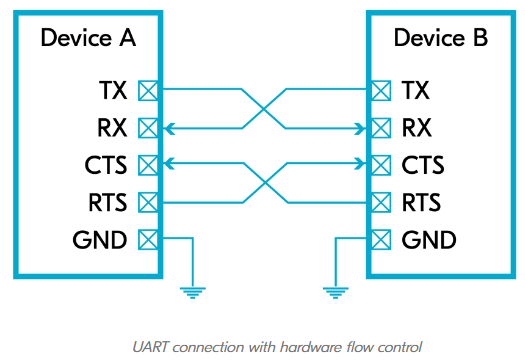
There is a UART port on the off-board MCU, which has 3 pins. do I only need to find out the 3 (or 2?) pins on the eval. board to connect?
In the "User Guide" P8, it reads that user should disable "Dynamic Hardware Flow Control (HWFC) handling" in order to use the P0.05 and P0.07, by sending DTR signals, but i didn't find much information about DTR and don't know how to send out it to the interface MCU on the eval. board.
There is a simlar topic:
About hardware flow control - Nordic Q&A - Nordic DevZone - Nordic DevZone (nordicsemi.com)
but the answer is not available.
I also found another related thread , but I am not sure that is exactly the same problem.
thanks!