Use FFT to handle MEMS microphone data

Hi Nordic,

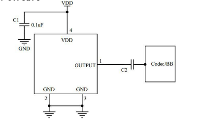
The proposed approach involves capturing ambient sound from the surroundings to achieve different LED display effects. The current plan is to use an Analog-to-Digital (AD) converter to collect output from MEMS microphones. Subsequently, Fast Fourier Transform (FFT) will be applied to analyze the frequency components of the sound, enabling the implementation of distinct LED display effects based on the frequency variations.

I am not entirely certain whether the ADC of the nRF52832 can achieve this effect. Also, is this approach feasible?

  • Essentially you should scale this setting based on the frequency ranges you are interested in, and how often you want to get a new FFT reading. Using a larger sample size allows you to capture lower frequencies, but you will get less updates per second. 

    My previous statement may have had some misunderstandings regarding FFT processing. In the FFT example in the SDK, it requires filling in 128 data points to obtain 64 data points. If I want to process an audio signal with a maximum frequency of 5 kHz, then the sampling rate needs to be at least 10 kHz. This means that at a frequency of 10 kHz, 128 ADC samples need to be obtained every 0.1 ms for the FFT to produce correct results. I have two questions to address: one is how do I create a timer for 0.1 ms? Additionally, can 128 data points be collected by the ADC within 0.1 ms?

  • Hi 

    I think the most natural way to implement this is to run the ADC at 10kHz, and simply set an ADC buffer size of 128 samples. Once one buffer is full you hand it over to the FFT processing function, and provide a second 128 sample buffer to the ADC. 

    Then you will get a new 128 byte buffer for processing every 12.8ms (1 sec / 10.000Hz * 128 samples)

    This means you will get a new FFT result at a rate of 78Hz, which would probably be enough to provide smooth feedback for the LED display algorithms? 

    Best regards
    Torbjørn

  • I think the most natural way to implement this is to run the ADC at 10kHz, and simply set an ADC buffer size of 128 samples. Once one buffer is full you hand it over to the FFT processing function, and provide a second 128 sample buffer to the ADC.

    So, you mean that collecting ADC data once every 0.1ms is sufficient to obtain processing results through FFT? I thought it was necessary to collect 128 data points continuously within 0.1ms. In that case, how should I use a 0.1ms timer? The minimum time for timers in the SDK is 1ms.

  • Hi 

    If you sampled 128 data points every 100us you would be massively oversampling the audio signal, this wouldn't give you any meaningful results. 

    Put another way, you can't run FFT on a single audio sample. You need an array of samples to get some frequency content. 

    You can look at the timer example in the SDK for help on setting up a TIMER module. These modules can run up to 16MHz clock frequency, and as such can be used for very accurate timing.

    For 100us timing the code should look something like this:

    const nrf_drv_timer_t TIMER_LED = NRF_DRV_TIMER_INSTANCE(0);
    
    /**
     * @brief Handler for timer events.
     */
    void timer_led_event_handler(nrf_timer_event_t event_type, void* p_context)
    {
        static uint32_t i;
        uint32_t led_to_invert = ((i++) % LEDS_NUMBER);
    
        switch (event_type)
        {
            case NRF_TIMER_EVENT_COMPARE0:
                bsp_board_led_invert(led_to_invert);
                break;
    
            default:
                //Do nothing.
                break;
        }
    }
    
    
    /**
     * @brief Function for main application entry.
     */
    int main(void)
    {
        uint32_t time_us = 100; //Time (in microseconds) between consecutive compare events.
        uint32_t time_ticks;
        uint32_t err_code = NRF_SUCCESS;
    
        //Configure all leds on board.
        bsp_board_init(BSP_INIT_LEDS);
    
        //Configure TIMER_LED for generating simple light effect - leds on board will invert his state one after the other.
        nrf_drv_timer_config_t timer_cfg = NRF_DRV_TIMER_DEFAULT_CONFIG;
        err_code = nrf_drv_timer_init(&TIMER_LED, &timer_cfg, timer_led_event_handler);
        APP_ERROR_CHECK(err_code);
    
        time_ticks = nrf_drv_timer_us_to_ticks(&TIMER_LED, time_us);
    
        nrf_drv_timer_extended_compare(
             &TIMER_LED, NRF_TIMER_CC_CHANNEL0, time_ticks, NRF_TIMER_SHORT_COMPARE0_CLEAR_MASK, true);
    
        nrf_drv_timer_enable(&TIMER_LED);
    
        while (1)
        {
            __WFI();
        }
    }

    Best regards
    Torbjørn

  • Thank you for your answer. I will test according to the solution you provided. If I have further questions, I will consult you later.

Related