Clarifications about partitions structure

Good morning!

I hope you will forgive my trivial question but I am a beginner.
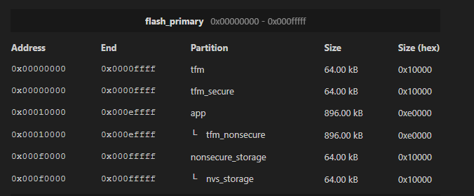
I don't quite understand the partition structure presented in the "NVS" example. Using the devicetree gui I get the following figure:

I'm developing an application that would store GNSS coordinates in internal flash. I actually can only use 32kb (7 + 1 pages) and I would like to enlarge the storage partition.

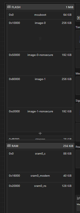
I actually have mcoboot, image-0, image-0 non secure, image-1, image-1 non secure and storage. Which partitions can I remove to enlarge my storage partition? Can you please explain the meaning of the other partitions?

Excuse me but I tried to read the documentation but I'm very confused.

Thank you in advance!

Regards.

Cristiano

  • Hi Sigurd!

    Thank you for your reply.

    I would like to ask you if there a way to better understand the meaning of all the partitions I see in memory report.

    Reading the nRF9160 memory by nRF Programmer with these settings:

    CONFIG_BOOTLOADER_MCUBOOT=y
    CONFIG_PM_PARTITION_SIZE_NVS_STORAGE=0x10000

    I see something like this:

    Instead, with these settings (I guess bootloader is not enabled),

    #CONFIG_BOOTLOADER_MCUBOOT=y                       
    CONFIG_PM_PARTITION_SIZE_NVS_STORAGE=0x10000

    I see this:

    It seems the CONFIG_PM_PARTITION_SIZE_NVS_STORAGE=0x10000 works also with bootloader not enabled. This is the memory report:

    So, in this second case, I'm not using bootloader... Do you confirm?

    Thank you again!

    Cristiano

  • In the second case you do not use a bootloader, that is correct.

    I think that TF-M (building with _ns) also enables the partition manager, which is why you still get a partition manager report without MCuboot

Related