Problem with hight conspumtion in System on mode

Hello, I am currently working on a custom board that contains the E73-2G4M08S1C module.
This module contains the nRF52840 chip. My goal is to exit System On periodically every 2 seconds.
I fulfilled this task, but the device consumes 600uA in System On mode, which is quite a lot.
I ran the same code on nRF52840 DK and the consumption in System On mode was 6uA, which is the expected result.
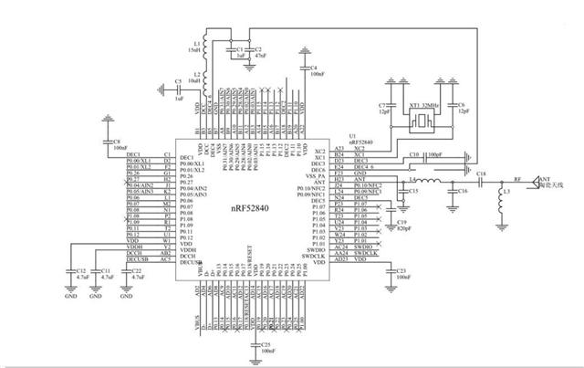
I really don't know where the problem could be. And I would appreciate any help :) I am attaching the scheme and the used code to the attachments.


  • R1 (10k) in parallel with R2&R4 (10k+10k=20k) gives 5k. 5k at 3v consumes 600uA, Perhaps IO 0.08 pin is being left driven high which therefore consumes 600uA so maybe try keeping IO 0.08 low.

    Also if IO 1.13 is driven high and either IO 0.30 or IO 0.31 is driven low at the same time then that will consume around 630uA.

  • Sure! Here's the corrected version of your sentence:

    "The error I reported is probably not hardware-related, but rather a bad `proj.conf` setting. On the nRF52840 DK, I have the basic settings as in the example in the system off folder. However, on the E73-2G4M08S1C module, I have to add a few extra lines because of the crystal to be able to flash the program at all. On the DK, I measured 5 µA in System off, not 6 µA. In System on, the consumption was 8 µA.

    On my board, after disconnecting the Segger, I measured 16 µA in System off and 550 µA in System on.

    I tried installing a new board where I only had the E73-2G4M08S1C module, Header J1 and J2, D1, C4, C5, R5, C2, and C6. In this mode, I measured 0.8 µA in System off and 460 µA in System on, which is still extremely high, considering that almost nothing is installed. I looked at the diagram of the module provided by the manufacturer, but I didn’t find anything unusual. I supply 4V to the device from an 18650 Li-Ion battery."


    Modul E73-2G4M08S1C:


    Extra lines for E73-2G4M08S1C:

    CONFIG_COUNTER=y
    CONFIG_UART_CONSOLE=n
    CONFIG_RTT_CONSOLE=y
    CONFIG_CLOCK_CONTROL=y
    CONFIG_CLOCK_CONTROL_NRF=y
    CONFIG_CLOCK_CONTROL_NRF_K32SRC_RC=y
    CONFIG_CLOCK_CONTROL_NRF_K32SRC_XTAL=n
    CONFIG_CLOCK_CONTROL_NRF_K32SRC_SYNTH=n
    CONFIG_CLOCK_CONTROL_NRF_K32SRC_500PPM=y
    CONFIG_CLOCK_CONTROL_NRF_K32SRC_RC_CALIBRATION=y
    CONFIG_CLOCK_CONTROL_NRF_CALIBRATION_LF_ALWAYS_ON=y
    CONFIG_LOG=y
    CONFIG_RTT_TX_RETRY_CNT=3
    CONFIG_RTT_TX_RETRY_DELAY_MS=1
    CONFIG_LOG_BACKEND_RTT=y
    CONFIG_LOG_BACKEND_RTT_MODE_BLOCK=y
    CONFIG_LOG_MODE_IMMEDIATE=y


    I had a consumption of 275 µA on the RST pin, which is probably not right.
  • I have log 0 set by default on all pins, except for the RGB, where I have log 1 set (I switch to log 0 to turn on the LED lights).

  • Maybe this is an issue: "I supply 4V to the device from an 18650 Li-Ion battery". The first schematic posted shows VIN connected to VDD; 4 V exceeds the absolute maximum rating for VDD and will have consequences. For above 3.6V the VDDH supply should be used, not VDD.

  • Thanks Hugh for pointing out. I was looking at the last schematics but couldn't see if the power supply connected to VDDH or VDD.  @Peter: if you want to connect to 4V power supply you would need to connect to VDDH and you need to follow the schematic for supplying to VDDH. Otherwise you would need to have a converter to get down to maximum 3.6V. 

    On the DK system OFF current should be less than 2uA. There could be an issue with your measurement. Please check try to use battery as the power supply as USB supply may create noise. 

Related