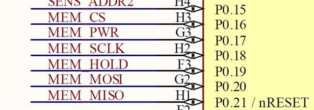
Hi, in our project we use the nRF52832 and a external flash memory MX25L3206E connected on this pins:

Take note in this project we also use SPIM0 to manage an IMU and SPIM2 to flash with this configuration:
//! GPIO FLASH power port number
#define HARDWARE_INIT_FLASH_PORT_NUMBER                                     0
//! GPIO FLASH power pin number
#define HARDWARE_INIT_FLASH_POWER_PIN_NUMBER                                17
//! GPIO FLASH write protect (WP) pin number
#define HARDWARE_INIT_FLASH_WP_PIN_NUMBER                                   5
//! GPIO FLASH hold pin number
#define HARDWARE_INIT_FLASH_HOLD_PIN_NUMBER                                 19

//! SPI FLASH MEMORY port number
#define HARDWARE_INIT_FLASH_SPI_PORT_NUMBER                                 0
//! SPI FLASH MEMORY CS pin number
#define HARDWARE_INIT_FLASH_SPI_CS_PIN_NUMBER                               16
//! SPI FLASH MEMORY SCLK pin number
#define HARDWARE_INIT_FLASH_SPI_SCLK_PIN_NUMBER                             18
//! SPI FLASH MEMORY MOSI pin number
#define HARDWARE_INIT_FLASH_SPI_MOSI_PIN_NUMBER                             20
//! SPI FLASH MEMORY MISO pin number
#define HARDWARE_INIT_FLASH_SPI_MISO_PIN_NUMBER                             21

//! SPI KX122 ACCELEROMETER SPI port number
#define HARDWARE_INIT_KX122_SPI_PORT_NUMBER                                 0
//! SPI KX122 ACCELEROMETER CS pin number
#define HARDWARE_INIT_KX122_SPI_CS_PIN_NUMBER                               4
//! SPI KX122 ACCELEROMETER MISO pin number
#define HARDWARE_INIT_KX122_SPI_MISO_PIN_NUMBER                             26
//! SPI KX122 ACCELEROMETER MOSI pin number
#define HARDWARE_INIT_KX122_SPI_MOSI_PIN_NUMBER                             25
//! SPI KX122 ACCELEROMETER SCLK pin number
#define HARDWARE_INIT_KX122_SPI_SCLK_PIN_NUMBER                             11
//! INT1 KX122 ACCELEROMETER interruption 1 pin number
#define HARDWARE_INIT_ACC_INT1_PIN_NUMBER                                   30
//! INT2 KX122 ACCELEROMETER interruption 2 pin number
#define HARDWARE_INIT_ACC_INT2_PIN_NUMBER                                   31

	{
		.misoPinIdentifier = HARDWARE_INIT_KX122_SPI_MISO_PIN_NUMBER,
		.misoPortConfig = HARDWARE_INIT_KX122_SPI_PORT_NUMBER,
		.mosiPinIdentifier = HARDWARE_INIT_KX122_SPI_MOSI_PIN_NUMBER,
		.mosiPortConfig = HARDWARE_INIT_KX122_SPI_PORT_NUMBER,
		.sclkPinIdentifier = HARDWARE_INIT_KX122_SPI_SCLK_PIN_NUMBER,
		.sclkPortConfig = HARDWARE_INIT_KX122_SPI_PORT_NUMBER,
		.ccsPinIdentifier = HARDWARE_INIT_KX122_SPI_CS_PIN_NUMBER,
		.ccsPortConfig = HARDWARE_INIT_KX122_SPI_PORT_NUMBER,
		.spiFrequency = HAL_SPI_FREQUENCY_1M,
		.spiClockPolarity = HAL_SPI_CPOL_LOW,
		.spiClockPhase = HAL_SPI_CPHA_LOTOHI,
		.spiMasterInstance = NRFX_SPIM_INSTANCE(0)
	},
	{
		.misoPinIdentifier = HARDWARE_INIT_FLASH_SPI_MISO_PIN_NUMBER,
		.misoPortConfig = HARDWARE_INIT_FLASH_SPI_PORT_NUMBER,
		.mosiPinIdentifier = HARDWARE_INIT_FLASH_SPI_MOSI_PIN_NUMBER,
		.mosiPortConfig = HARDWARE_INIT_FLASH_SPI_PORT_NUMBER,
		.sclkPinIdentifier = HARDWARE_INIT_FLASH_SPI_SCLK_PIN_NUMBER,
		.sclkPortConfig = HARDWARE_INIT_FLASH_SPI_PORT_NUMBER,
		.ccsPinIdentifier = HARDWARE_INIT_FLASH_SPI_CS_PIN_NUMBER,
		.ccsPortConfig = HARDWARE_INIT_FLASH_SPI_PORT_NUMBER,
		.spiFrequency = HAL_SPI_FREQUENCY_1M,
		.spiClockPolarity = HAL_SPI_CPOL_LOW,
		.spiClockPhase = HAL_SPI_CPHA_LOTOHI,
		.spiMasterInstance = NRFX_SPIM_INSTANCE(2)
	}
This is the prj.conf of the project:
# Drivers selection

CONFIG_GPIO=y
CONFIG_GPIO_AS_PINRESET=n
CONFIG_SERIAL=y
# UARTE
#CONFIG_NRFX_UARTE1=n
#CONFIG_NRFX_UARTE0=y
CONFIG_LOG=n
CONFIG_LOG_DEFAULT_LEVEL=3
CONFIG_WATCHDOG=y

CONFIG_ADC=y
CONFIG_ADC_ASYNC=y
CONFIG_ADC_NRFX_SAADC=y

CONFIG_PINCTRL=y
CONFIG_I2C=y
#CONFIG_NRFX_TWIM1=y
CONFIG_FLASH=y
CONFIG_SPI=y
CONFIG_SOC_NRF52832_ALLOW_SPIM_DESPITE_PAN_58=y
CONFIG_NRFX_SPIM0=y
CONFIG_NRFX_SPIM2=y

CONFIG_FLASH_PAGE_LAYOUT=y
CONFIG_MPU_ALLOW_FLASH_WRITE=y
CONFIG_SOC_FLASH_NRF_EMULATE_ONE_BYTE_WRITE_ACCESS=y

CONFIG_REBOOT=y #n

# Power management
# CONFIG_PM=y
# CONFIG_PM_DEVICE=y
# CONFIG_POWEROFF=y

# Interrupts
# CONFIG_DYNAMIC_INTERRUPTS=n
# CONFIG_UART_INTERRUPT_DRIVEN=n
# CONFIG_IRQ_OFFLOAD=n

# Stacks and heaps
# This configuration reserve 20K of RAM to HEAP, this project only has 64K
# and all the code is the 98% of the RAM so we can not declare so much heap
CONFIG_HEAP_MEM_POOL_SIZE= 8000
#CONFIG_HEAP_MEM_POOL_SIZE= 6144
CONFIG_MAIN_STACK_SIZE=1024
CONFIG_SYSTEM_WORKQUEUE_STACK_SIZE=4096
#CONFIG_NET_TX_STACK_SIZE=512
#ONFIG_NET_RX_STACK_SIZE=512
# CONFIG_NET_MGMT_EVENT_STACK_SIZE=2048

# Memory protection
# CONFIG_THREAD_STACK_INFO=n
# CONFIG_THREAD_CUSTOM_DATA=n
# CONFIG_FPU=n

# BLE configuration
CONFIG_BT=y
CONFIG_SETTINGS=y
CONFIG_BT_PERIPHERAL=y
CONFIG_BT_GATT_DYNAMIC_DB=y

#CONFIG_BT_PERIPHERAL_PREF_MIN_INT=6
#CONFIG_BT_PERIPHERAL_PREF_MAX_INT=9
#CONFIG_BT_PERIPHERAL_PREF_LATENCY=99
#CONFIG_BT_PERIPHERAL_PREF_TIMEOUT=400
#CONFIG_BT_GAP_AUTO_UPDATE_CONN_PARAMS=y

CONFIG_BT_DEVICE_NAME="Tarsos Device"

CONFIG_BT_L2CAP_TX_MTU=252
CONFIG_BT_BUF_ACL_TX_SIZE=251
CONFIG_BT_BUF_ACL_RX_SIZE=502

#CONFIG_BT_SMP=y
#CONFIG_BT_SIGNING=y
#CONFIG_BT_PERIPHERAL=y
#CONFIG_BT_DIS=y
#CONFIG_BT_ATT_PREPARE_COUNT=5
#CONFIG_BT_BAS=y
#CONFIG_BT_HRS=y
#CONFIG_BT_IAS=y
#CONFIG_BT_PRIVACY=y
#CONFIG_BT_DEVICE_APPEARANCE=833
#CONFIG_BT_DEVICE_NAME_DYNAMIC=y
#CONFIG_BT_DEVICE_NAME_MAX=65

#CONFIG_BT_KEYS_OVERWRITE_OLDEST=y
#CONFIG_BT_SETTINGS=y

# Debug configuration
CONFIG_DEBUG=y
CONFIG_DEBUG_OPTIMIZATIONS=y
CONFIG_DEBUG_THREAD_INFO=y
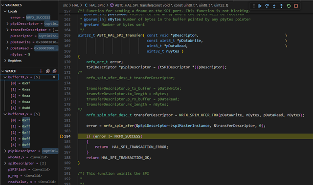
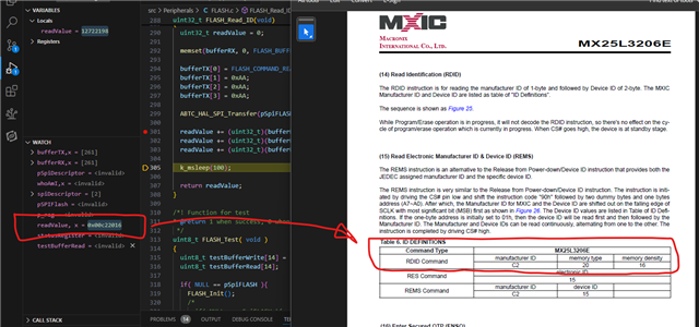
The problem is that the IMU works fine due to it rsponse his ID number and other data, but when we try to comunicate with the flash memory to see the iID number it return in our buferRX all ones,

Could you any chech this and explain why SPIM0 works fine and SPIM2 no?
Many thanks in advance.


