Voltage drop triggers BOR reset; MCU occasionally completely freezes

Hi,

I'm facing a critical issue with our sensor's power setup and would really appreciate any insights or suggestions.

Our sensor is currently using a CR2477 battery, and I'm running into problems due to the load resistance of the battery. When transmitting data, especially after switching from PHY_1M to PHY_CODED_S8, the battery voltage drops enough to trigger the Brown Out Reset (BOR), which then resets the sensor. I noticed this specifically with PHY_CODED_S8 since the transmission takes longer, causing a larger voltage drop.

Occasionally, the sensor also completely hangs—even after the voltage recovers back to 3V again. From my understanding, this seems to be expected behavior with the nRF52 when experiencing a brownout, as only a full power cycle can bring it back online - why is that so and can I prevent this?

Has anyone experienced similar issues or found software and/or hardware solutions to prevent these resets? I’d be especially interested in any software adjustments to handle the BOR more gracefully or hardware tips for improving power stability with high load resistance batteries in future versions of the sensor.

Currently I'm powering directly via the CR2477 to VDD and VDDHV with a 47µF and a 4.7µF capacitor (and of course the standard 100nF on each power input)
DCDC on µC is enabled

Setup:
NRF52840, NCS2.6.1, Zephyr

Thanks in advance for any advice!

Best Regards,
Phobios

  •  Hi  ,

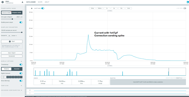
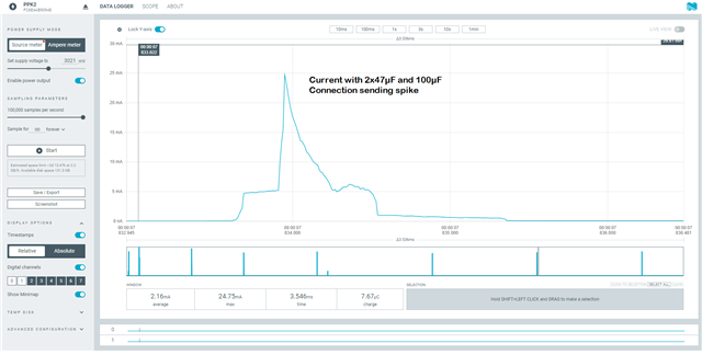
    sry I have to dig out the post again, but I've now prepared some Sensors with additional 100µF/6V3 and 47µF/10V ceramic capacitors. I've made some comparison measurements with NRF Power Profiler 2. I'm a little puzzled, cause with the additional capacitors, the current spikes are higher, than without.

    Measurement 1: Sensor with 47µF

    Measurement 2: Sensor with 2x47µF and 100µF

    The really odd thing is: If I meassure the voltage drop, the more capacitors helps (and I've not swaped any measurements, I checked it three times)

    Any suggestions?

    Thanks and Best Regards,

    Phobios

  • The curves are as expected; pity the PPK-2 doesn't allow voltage measurement, and thence power calculations, which would illustrate why. Current is a don't care here, voltage dip is all that matters as the voltage dip is what causes brownout issues. For a given power burst (typically BLE Tx transmit) higher available current (bigger caps) means lower voltage dip: volts x amps will be similar in both cases, except losses will be higher with the smaller capacitance as more current during the pulse is sourced via the battery resistive internals which is bad for the battery, bad for the planet and reduces anticipated product life.

  • I should clarify the required PPK2 connections, just in case not obvious. The coin call connects to PPK2 VIN and GND in Ampere Mode with no capacitors on the battery; the extra capacitors should be connected between VOUT and GND as the required measurement is just the battery current, not the battery current plus extra capacitor current. I wonder if in the measurements shown above the capacitors are instead on battery and VIN.

Related