GPIO P1.02 on nRF54L15 doesn't work.

Hi.

I made a board with nRF54L15.

I would like to use P0.01 on nRF54L15 as GPIO output., but I failed to confirm P0.01 turn high.

Then, I asked nordic AI anything to solve this problem.

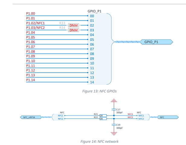
AI recommended to add below in prj.conf, because nRF54L15DK use P1.02 as NFC1 by default.

CONFIG_NFCT_PINS_AS_GPIOS=y

Not only this, I also added below to devicetree according to AI

/{
	user_dbg_pin: user-dbg-pin {
		compatible = "nordic,gpio-pins";
		gpios = <&gpio1 2 GPIO_ACTIVE_HIGH>;
		status = "okay";
	};
}

&gpio1 {
	status = "okay";
};

&gpiote20 {
	status = "okay";
};

&uicr {
    nfct-pins-as-gpios;
};

and, main.c

static const struct gpio_dt_spec pin_dbg = GPIO_DT_SPEC_GET_OR(DT_NODELABEL(user_dbg_pin), gpios, {0});

~~~~~~~~~~~~~~~~~~~~

if (pin_dbg.port) {
	gpio_pin_configure_dt(&pin_dbg, GPIO_OUTPUT_INACTIVE);
}

~~~~~~~~~~~~~~~~~~~~
gpio_pin_set_dt(&pin_dbg, 0);

gpio_pin_set_dt(&pin_dbg, 1);

But, I couldn't find GPIO 1.02 change.

Would you tell me anything to solve ?

Best regards.

  • I'll put prj.conf in my application below.

    #
    # Copyright (c) 2024 Nordic Semiconductor
    #
    # SPDX-License-Identifier: LicenseRef-Nordic-5-Clause
    #
    
    # Step 1 - Enable nrfx drivers #
    CONFIG_NRFX_GRTC=y
    #CONFIG_NRFX_SAADC=y
    #CONFIG_NRFX_GPPI=y
    #CONFIG_NRFX_TIMER2=y
    CONFIG_NRFX_TIMER22=y
    
    CONFIG_GPIO=y
    CONFIG_I2C=y
    
    
    CONFIG_COMPILER_OPT="-DARM_TABLE_TWIDDLECOEF_F32_64 -DARM_TABLE_BITREVIDX_FLT_64 -DARM_TABLE_TWIDDLECOEF_F32_64 -DARM_TABLE_TWIDDLECOEF_RFFT_F32_128 -DARM_MATH_CM4"
    CONFIG_CMSIS_DSP=y
    CONFIG_DSP=y
    CONFIG_CMSIS_DSP_FASTMATH=y
    CONFIG_CMSIS_DSP_STATISTICS=y
    CONFIG_CMSIS_DSP_MATRIX=y
    #CONFIG_NEWLIB_LIBC=y
    #CONFIG_CMSIS_DSP_BAYES=y
    CONFIG_CMSIS_DSP_TRANSFORM=y
    CONFIG_CMSIS_DSP_SUPPORT=y
    CONFIG_CMSIS_DSP_COMPLEXMATH=y
    CONFIG_CMSIS_DSP_CONTROLLER=y
    CONFIG_DSP_BACKEND_CMSIS=y
    CONFIG_FPU=y
    
    CONFIG_LOG=y
    
    #added in order to get the thread name printed in the assertion log.
    CONFIG_THREAD_NAME=y
    CONFIG_MAIN_STACK_SIZE=2048
    
    CONFIG_ADC=y
    
    # Step 2 - Enable Bluetooth #
    CONFIG_BT=y
    CONFIG_BT_DEVICE_NAME="sample"
    CONFIG_BT_PERIPHERAL=y
    CONFIG_BT_EXT_ADV=y
    CONFIG_BT_BROADCASTER=y
    CONFIG_BT_OBSERVER=y
    
    # Step 3 - Enable Coded PHY for Bluetooth LE #
    CONFIG_BT_USER_PHY_UPDATE=y
    CONFIG_BT_CTLR_PHY_CODED=y
    
    # Step 4 - Enable Bluetooth LE Extended Advertising #
    CONFIG_BT_EXT_ADV=y
    CONFIG_BT_CTLR_ADV_EXT=y
    CONFIG_BT_EXT_ADV_MAX_ADV_SET=2
    CONFIG_BT_CTLR_ADV_DATA_LEN_MAX=251
    
    # STEP 2.2 - Enable FOTA over Bluetooth LE
    CONFIG_NCS_SAMPLE_MCUMGR_BT_OTA_DFU=y
    CONFIG_MCUBOOT_BOOTUTIL_LIB=y
    CONFIG_MCUBOOT_GENERATE_CONFIRMED_IMAGE=y
    CONFIG_MCUBOOT_EXTRA_IMGTOOL_ARGS="--confirm"
    
    CONFIG_WATCHDOG=n
    CONFIG_FLASH=n
    CONFIG_PM=n
    CONFIG_DYNAMIC_INTERRUPTS=n
    CONFIG_IRQ_OFFLOAD=n
    CONFIG_THREAD_STACK_INFO=n
    CONFIG_THREAD_CUSTOM_DATA=n
    CONFIG_BOOT_BANNER=n
    CONFIG_BOOT_DELAY=0
    #CONFIG_CONSOLE=n
    #CONFIG_UART_CONSOLE=n
    #CONFIG_STDOUT_CONSOLE=n
    #CONFIG_PRINTK=n
    CONFIG_EARLY_CONSOLE=n
    CONFIG_SIZE_OPTIMIZATIONS=y
    
    CONFIG_BT_HCI_CORE_LOG_LEVEL_OFF=y
    
    CONFIG_CLOCK_CONTROL_NRF_K32SRC_RC=y
    CONFIG_CLOCK_CONTROL_NRF_K32SRC_RC_CALIBRATION=y
    CONFIG_CLOCK_CONTROL_NRF_K32SRC_500PPM=y
    CONFIG_CLOCK_CONTROL_NRF_K32SRC_XTAL=n
    CONFIG_MPSL_HFCLK_LATENCY=1600
    
    # Step 6 - disable NFC for out-of-band pairing #
    CONFIG_NFCT_PINS_AS_GPIOS=y

  • Hello,

    Your approach seems correct. I think you need to rework on hardware also. On the board you are using, R21 and R22 should not be connected; and R33 and R34 must be shorted with 0 ohm resistors.

    This will physically reassign the pins from NFC to GPIO.

    source: NFC antenna interface

  • Hi.

    Your explanatiom seemes correct too.
    But, I could confirm with minimum configuration project based on a blinky sample project.
    I altered the blinky project to add

    CONFIG_NFCT_PINS_AS_GPIOS=y

    in prj.conf and

    &led0 {
    	gpios = <&gpio1 2 0>;
    };
    
    &uicr {
        nfct-pins-as-gpios;
    };

    in devicetree.overlay

    But, I couldn't confirm  with quoted one.

    'll put prj.conf in my application below.

    I'll put two hex file, the minimum(blinky based)  and current application .

    minimum

    6232.merged.hex

    current app (prj.conf and overlay in first comment)

    2526.app.hex

    Would you tell me anything to help 
    (For example, the output file of port assignment,
    the comparison between minimum and app) ?

    Best regards.

  • Hello,

    Is this your custom board? Is any other peripheral assigned as the same pin as P1.02? Somewhere in the project is LED0 defined as other pin number? 

    If you want can share me the application file or at least the board file of your application?

  • Hi.

    I saw the problem with a custom board first, which no other peripheral assigned as P1.02.
    Backing to my application, I missed the assignment of P1.02 as &led1 and &led0.
    Fixing it, I confirmed the GPIO function with my application.

    Thanks.

Related