Hello Nordic Team,
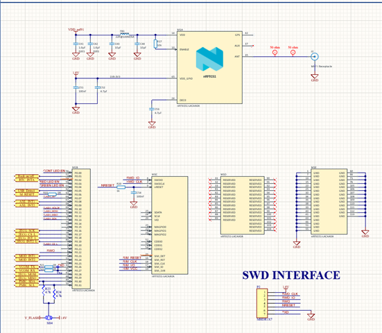
We have developed a custom PCB using nRF9151 and nPM1300.
Sometimes, the PMIC powers up and works normally; other times it doesn’t start at all.
It occasionally works only when connected to a debugger via SWD (SDIO, SCLK, RESET).
Hardware Configuration
-
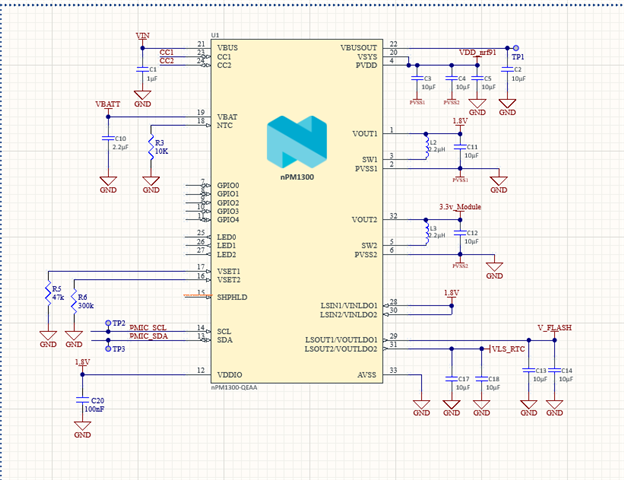
Battery: 3.7 V Li-Po (600 mAh)
-
PMIC Connections:
-
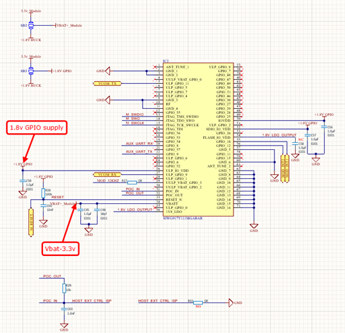
VSYS → nRF9151 VDD
-
BUCK1 (1.8 V) → nRF9151 GPIO (VDD_GPIO) + I²C pull-ups
-
BUCK2 (3.3 V) → other modules
-
LDO1/LDO2 → additional 1.8 V + RTC supply
-
-
I²C Pull-ups: 4.7 kΩ to 1.8 V (BUCK1 output)
Issue Summary
-
Sometimes PMIC powers the system normally.
-
Sometimes it does not start from battery.
-
When connected via nRF Connect / Debugger, PMIC initializes correctly (BUCK1/2 + LDOs output voltages).
-
When running standalone (battery only), PMIC occasionally fails to power up.
-
Software logs:
-
“PMIC device not ready”
-
“Charger not ready”
-
“Fuel gauge init failed”
(These failures occur randomly on cold boot.)
-
Question
Do we need a specific power-up sequence between nRF9151 and nPM1300?
Any known conditions or timing dependencies that could cause the PMIC not to start properly?
k_msleep(1000);

if (!device_is_ready(pmic)) {
    printk("PMIC device not ready.\n");
    return -1;
}
if (!device_is_ready(charger)) {
    printk("Charger device not ready.\n");
    return -1;
}

if (fuel_gauge_init(charger) < 0) {
    printk("Could not initialize fuel gauge.\n");
    return -1;
}

regulator_enable(buck1);
regulator_enable(buck2);
regulator_enable(ldo1);
regulator_enable(ldo2);
&i2c2 {
    status = "okay";
};

#include <dt-bindings/regulator/npm1300.h>

&arduino_i2c {
    npm1300_ek_pmic: pmic@6b {
        compatible = "nordic,npm1300";
        reg = <0x6b>;

        npm1300_ek_regulators: regulators {
            compatible = "nordic,npm1300-regulator";

            npm1300_ek_buck1: BUCK1 {
                regulator-init-microvolt = <1800000>;
            };

            npm1300_ek_buck2: BUCK2 {
                regulator-init-microvolt = <3300000>;
                /delete-property/ enable-gpios;
            };

            npm1300_ek_ldo1: LDO1 {
                regulator-init-microvolt = <1800000>;
                regulator-initial-mode = <NPM1300_LDSW_MODE_LDSW>;
            };

            npm1300_ek_ldo2: LDO2 {
                regulator-init-microvolt = <1800000>;
                regulator-initial-mode = <NPM1300_LDSW_MODE_LDSW>;
            };
        };

        npm1300_ek_charger: charger {
            compatible = "nordic,npm1300-charger";
            term-microvolt = <3600000>;
            current-microamp = <150000>;
            charging-enable;
        };
    };
};
Sometimes the above sequence fails at different steps (PMIC / Charger / Fuel gauge), though it works fine once in a while.
Observation
When debugger is attached, I²C communication and PMIC initialization always succeed — which suggests possible startup timing, reset synchronization, or power-rail sequencing issue between nRF9151 and nPM1300.
Could you please guide us on:
-
Correct power-up timing or initialization order?
-
Any recommended delay or condition to check before I²C access?
-
Whether PMIC requires an external enable or wake sequence from nRF9151?