nPM1300 VBAT is in pinging mode (not DC / steady state) after VBUS reaches valid range

I would like to check if our observation with nPM1300's VBAT node is expected per the IC's design.

As a background, in our application ee use a low-leakage switch to isolate the battery from nPM1300's VBAT node.

1) Once the battery is isolated while VBUS=0V, the IC shuts down VSYS=0V and this is as expected.

2) Next, we apply VBUS=5.0V and the node VSYS settles to ~4.9V at which point our host can communicate

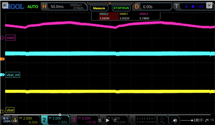
with the nPM1300 over i2C. What we observe at this phase is that node VBAT generates narrow pulses 

~200us in duration at a repetition rate of ~500ms with peak amplitude of ~5V. I term this behavior as "battery pinging".    

3) The node VBAT becomes steady state ~4V once the host has configures the nPM1300 charger with charging parameters and enables charging.

Is the above battery pinging and battery connecting "normal behavior" and makes sense in terms of the nPM1300 design?

Is there a way to change the nPM1300 OTP memory to enable battery connection per default once the part starts up and without host intervention over i2C?

Thanks in advance, 

Kostas   

  • Hello Asbjørn,

    I appreciate your replies to my questions, the details you have provide are very valuable. I have taken note in regards to Q1 and Q2 and will apply changes in our host f/w accordingly.

    I hope that you will be able to help answer one more circuit detail specific to the battery charging in the nPM1300. As a background, we feed VBUS from a wireless charging receiver (AC/DC rectifier) and have observed temporal voltage modulation at the supply voltage side i.e. VBUS during stationary battery charging (in this scenario no external consumers are supplied from VSYS, nor DC/DC or LDO 1/2). 

    I wonder if this voltage modulation on VBUS is caused by the charger itself if the charging current is pulsatile over time, or if charging is interrupted periodically by the nPM1300 to take ADC measurements of VBAT and or IBAT?

    Have a good weekend!

    best regards,

    Kostas      


  • Hello Kostas,

    If I may ask what sort of modulation are you observing? Is it the same frequency as you have configured the ADC to measure?

    Is it related to TWI frequency? Is it related to wireless charging switching?

    How are you observing the modulation? Are you able to share plots from what you observe? 

    Best regards

    Asbjørn

  • Hello Asbjørn,

    I have attached a movie recording three traces and their time domain characteristics as the nMP1300 enters battery charging likely in trickle charge mode (fw to 20sec to see the temporal modulations).   

    VRECT in the top trace is the AC/DC rectifier output of the wireless power RX, that feeds a 5V buck regulator that has its output connected to nPM1300 VBUS input.

    The ADC measurement and data readout in the application is slow, at a rate of 1/5 seconds, it does not correlate to the rate of voltage modulation that I have seen. My current hypothesis is that is either caused by the buck regulator's switching scheme, or the nPM1300 charging logic especially if the charging algorithm cahrges the battery using a pulsatile current rather than DC.

    Your thoughts?

    Thanks and best regards,

    Kostas  


  • Hello Kostas,

    Here are my observations from the video:
    - It seems the VRECT starts this sequence of modulation. At 22-23 seconds of the video all three signals show a voltage drop. Is this when the charging engages? This stage lasts from 12 seconds until saw tooth ripple emerges on - Vrect and Vbat is showing repeatable small drops on the voltage.
    - At 34 seconds though, just before the saw tooth on Vrect, there's a really short pulse noticeable on all domains, see the one to the right here and after that the saw tooth start on Vrect. Vbdomains then show  
    - The saw tooth increases in frequency after a couple of seconds and not visible on Vrect after. The saw tooth is visible on Vbat until 46 seconds where it seems Vrect goes back up towards 6.2V. 
    - Another cycle of this starts at 1:09. 
    Q1: Again Vrect drops down to 4.1V from 6.2-6.3V. Is this dop expected from the buck that feeds VBUS?
    Q2: What does VBUS look like?
    Q3: Is the wireless charger able to deliver enough current to sustain this? Suspect that that VBUS drops as Vrect drops and it's not capable of delivering enough current. That's why there's a 2V drop on Vrect.
    Is it possible that the nPM1304 with the option of smaller charge currents could be an alternative for you?
    Best regards
    Asbjørn
  • Hello Asbjørn,

    Your observations are correct. The sawtooth-like fundamental frequency changes from ~4Hz to ~60Hz and the onset of VRECT rising up seems to be triggered in response to load current picking up on VSYS, or by Charger temporarily start/stopping injecting current into the battery. When VRECT drops below 5V the downstream DCDC regulator that feeds VBUS is no longer in regulation mode i.e. its output voltage VBUS simply tracks VRECT. This is caused by the wireless charger source impedance that varies across coupling distance and dynamics in the load that the nPM1300 plus downstream active consumers.

    The nPM1304 is not a better choice for our application because of lower max charging current and lack of the two internal LDOs.

    Can you please kindly clarify from the nPM1300 charge management and system monitor standpoint, what the battery voltage ADC measurement looks like on circuit level? Is the battery voltage measured in open-circuit conditions during charging (charging current stops, battery terminals disconnect from VSYS for a short period of time) and also what about during discharging (I can't imagine the battery disconnects to allow the battery to recover from load, but perhaps the disconnection time is super short) ?    

    Thanks and best regards,

    Kostas


Related