This post is older than 2 years and might not be relevant anymore
More Info: Consider searching for newer posts

Dependence between connection interval parameter and QDEC

Hi,

I have question related with some parameters of BLE transmision.

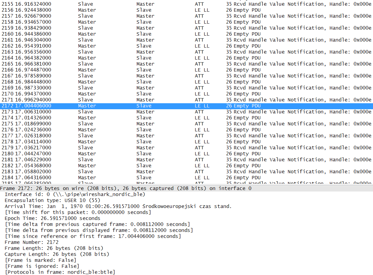
Connection interval in my project is set to 10 ms. Peripheral sends a notifications whenever the value of characteristic is changing - this interval is also set to 10 ms. So, I send one notification per single connection interval.

Whats more, I use a QDEC in my project (simplerdy mode) and I set pin P0.03 as a QDEC LED output to generate synchronized clock impulses.

I captured connectionless BLE link from one device to another. Please see a screenshot below:

image description

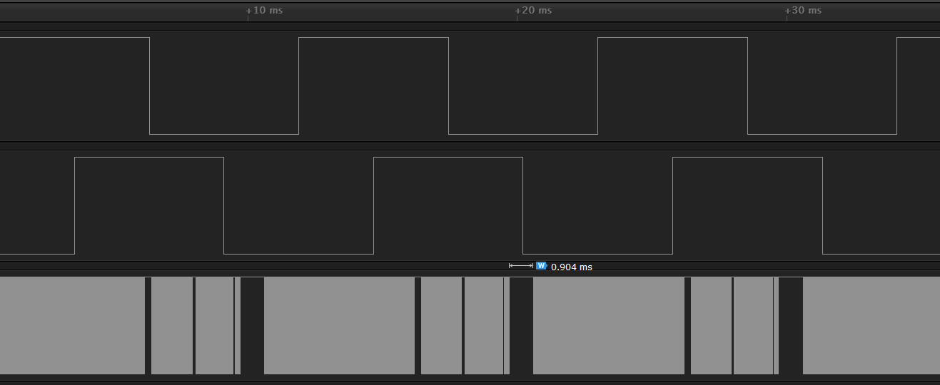
This is how looks waveform in that configuration - first and second lines are A and B signals from encoder, third is a sampling clock generated by the LED output:

image description

When I disable notification waveform looks like this:

image description

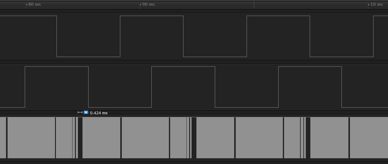
My main question is about LED output on these traces. They are generated according to parameters which I set in nrf_drv_config.h file. However in some periodic, regular intervals the line is hold for a some time in a high state. I guess that this is related with communication and connection interval. If the notifications are set, this time is around 0.9 ms, when they are not, the time is around 0.4 ms (connection interval parameter is still set to 10 ms). You can see these times on above waveforms.

This generates a problem for me, because I cannot count a encoder changes while LED output helds a high state.

Is it okay, that this occurs? Is it possible to decrease these times, if yes, how can I do that?

  • From infocenter:

    "If the SAMPLEPER value needs to be changed, the QDEC shall be stopped using the STOP task. SAMPLEPER can be then changed upon receiving the STOPPED event, and QDEC can be restarted using the START task. Failing to do so may result in unpredictable behaviour."

    So, where in my code should I enable and disable qdec to read measurements properly, but not allow a SoftDevice interrupt LED output?

  • Sorry for the bad response, I've been on vacation for the last two weeks. The example is kind of weird as it both produce the encoder output and then decodes it with the qdec. It may not be the best example to use for a real encoder, and I will see if we can improve this example. The way you use the encoder depends on your application. Instead of getting interrupt on every sample you may want to read the state of the of the accumulators with nrf_drv_qdec_accumulators_read(int16_t * p_acc, int16_t * p_accdbl) when you need to know how many transisitions have been made since last read, or you may want to set up the reportper to know when a certain number of transitions have been made. I suggest that you read the QDEC chapter in the Reference Manual to get a better understanding of how the decoder works.

Related