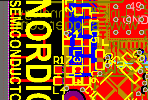
Hi, i am designing a board using balun in it. Also, i am going to use meander antenna of nordic dongle(reference image is attached). As i can see, there is no RF coplaner waveguide strip but there are RF traces connecting C6, C14, R17, L4. So, my questions are:
-
To connect C6, C14, R17, L4, do i need to calculate the trace width for 50 ohm impedance (RF connecting traces in dongle doesn't seem to have impedance of 50 ohm.)?
-
As per my understanding, in order to tune the antenna, i need to put the SMA coaxial connector before pi network or solder coaxial cable after cutting the trace before pi network. But i don't see any place for that in nordic Dongle design. How did nordic guys do that? i have following assumptions/ questions:
a. were these pi network footprints added to subsequent prototype after tuning done for previous one as there is no extra place for tuning connector or cable?
b. Even, if i provide place for a SMA coaxial connector before the pi network footprints, what would happen to the left space after removing SMA coaxial connector (adding trace of 50 ohm would take up space)? Can i move pi network close to balun (RF part) after removing coaxial connector as pi network is close to C6 in Nordic Dongle?
-
Do i really need pi network to tune this meander antenna of dongle or a shunt capacitor would be enough?
Note: I am new to all this stuff, so please spare me for my wrong assumptions/ questions and also, don't forget to correct me. There is not sufficient knowledge related to antenna tuning PROCEDURE for a layman like me. It'd be great, if nordic Guys would come up with simple and step by step guide for tuning (nWP-017 isn't enough).