
Can the nRF52 output the 32.768kHz clock on a GPIO. If so, do I need the 32.768kHz xtal, or can I output the generated clock from the 32MHz xtal? I need this clock to sync other ICs.
Can the nRF52 output the 32.768kHz clock on a GPIO. If so, do I need the 32.768kHz xtal, or can I output the generated clock from the 32MHz xtal? I need this clock to sync other ICs.
Let me try to do this tomorrow morning. Maybe we can do it.
Try this code
#define LFCLK_OUTPUT             (11U)
#define DELAYED_LFCLK_OUTPUT     (12U)


void start_timer(void)
{

        /* Start 16 MHz crystal oscillator */
    NRF_CLOCK->EVENTS_HFCLKSTARTED = 0;
    NRF_CLOCK->TASKS_HFCLKSTART    = 1;

    /* Wait for the external oscillator to start up */
    while (NRF_CLOCK->EVENTS_HFCLKSTARTED == 0)
    {
        // Do nothing.
    }

  NRF_TIMER1->MODE = TIMER_MODE_MODE_Timer;
  NRF_TIMER1->TASKS_CLEAR = 1;
  NRF_TIMER1->PRESCALER = 0;
  NRF_TIMER1->BITMODE = TIMER_BITMODE_BITMODE_16Bit;

    // Timer expires 1
  NRF_TIMER1->CC[0] = 244;  // expires  (1/4)*(1/16384) microseconds

}

void lfclk_config()
{
  NRF_CLOCK->LFCLKSRC = (CLOCK_LFCLKSRC_SRC_Xtal << CLOCK_LFCLKSRC_SRC_Pos);
  NRF_CLOCK->EVENTS_LFCLKSTARTED = 0;
  NRF_CLOCK->TASKS_LFCLKSTART = 1;
  while (NRF_CLOCK->EVENTS_LFCLKSTARTED == 0) {}

  NRF_RTC1->PRESCALER = 0; //1kHz frequency
  NRF_RTC1->EVTEN     = (RTC_EVTENSET_TICK_Msk ); /* event on COMPARE0 and TICK */

}


int main(void) {

  lfclk_config();

  start_timer();

  // configure GPIOTE
  NRF_GPIOTE->CONFIG[0] = ( (GPIOTE_CONFIG_MODE_Task      << GPIOTE_CONFIG_MODE_Pos)
                          | (LFCLK_OUTPUT                  << GPIOTE_CONFIG_PSEL_Pos)
                          | (GPIOTE_CONFIG_POLARITY_Toggle << GPIOTE_CONFIG_POLARITY_Pos) )
                          | (0 << GPIOTE_CONFIG_OUTINIT_Pos);

  // configure timer CC event to toggle  DELAYED_LFCLK_OUTPUT
  NRF_GPIOTE->CONFIG[1] = ( (GPIOTE_CONFIG_MODE_Task      << GPIOTE_CONFIG_MODE_Pos)
                          | (DELAYED_LFCLK_OUTPUT         << GPIOTE_CONFIG_PSEL_Pos)
                          | (GPIOTE_CONFIG_POLARITY_Toggle << GPIOTE_CONFIG_POLARITY_Pos) )
                          | (1 << GPIOTE_CONFIG_OUTINIT_Pos);

  // configure PPI  channel 2 convert timer CC event to GPIOTE task out
  NRF_PPI->CH[2].EEP    = (uint32_t)(&NRF_TIMER1->EVENTS_COMPARE[0]);
  NRF_PPI->CH[2].TEP    = (uint32_t)(&NRF_GPIOTE->TASKS_OUT[1]);
  NRF_PPI->CHENSET    |= PPI_CHENCLR_CH2_Msk;  // enable

  // configure PPI
  NRF_PPI->CH[0].EEP    = (uint32_t)(&NRF_RTC1->EVENTS_TICK);
  NRF_PPI->CH[0].TEP    = (uint32_t)(&NRF_GPIOTE->TASKS_OUT[0]);
  NRF_PPI->CHENSET      = PPI_CHENCLR_CH0_Msk;


  // configure PPI  channel 1 to clear timer counter
  NRF_PPI->CH[1].EEP    = (uint32_t)(&NRF_RTC1->EVENTS_TICK);
  NRF_PPI->CH[1].TEP    = (uint32_t)(&NRF_TIMER1->TASKS_CLEAR);
  NRF_PPI->CHENSET    |= PPI_CHENCLR_CH1_Msk;  // enable

  NRF_RTC1->TASKS_START = 1;
  NRF_TIMER1->TASKS_START = 1;               // Start TIMER1

    while (true)
    {
        __SEV();
        __WFE();
        __WFE();
    }
}
output is like below
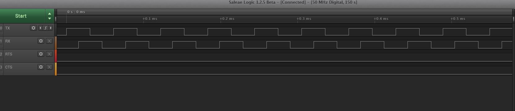
XOR both outputs and you should have LFCLK with required accuracy. Hopefully the propagation delays within the chip for rerouting events are negligible.
I understand the TIMER1 (HFCLK) is used to create the second signal, but XORing it with first signal which is generated from RTC (LFCLK). So the signal that is generated by XORing these two should have better accuracy.

I don' think that this will work; the two different clock frequencies (32.768kHz and 32.787kHz) drift over time.

are you sure they drift over time? these are outputs from two XTALs (HFCLK and LFCLK) you think XORing them will drift?
One is toggling a GPIO @ 16.384kHz; the other @ 16.394kHz, right? If you take a long capture, won't you see the pulses deviate from each other?