This post is older than 2 years and might not be relevant anymore
More Info: Consider searching for newer posts

Counter does not count correctly external signal

Hello, I'm having special SPI protocol which requires SPI Slave to toggle REDAY pin after every byte. I do test using 2 nRF52 boards. One is SPI master, another is slave. When I do it in SW then it works fine for multiple hours. There is a loop that SPI is set to receive 1B, then SW toggles RDY, then SPI is set again to receive 1B... But when I wanted to optimize and let HW count SPI_CLK and generate RDY it start to be unstable. It usually stops working within 3 minutes. With Saleae logic analyzer I discovered that READY pin is toggled one falling edge sooner.

The HW configuration is as follows:

  • I use in parallel my SPI_CLK with GPIOTE module. Falling edge is set to generate an EVENT.
  • Event is connected via PPI into COUNTER.
  • counter compare register CC[0] is set to 8 (falling edges).
  • Another PPI connects Counter COMPARE event into REDAY GPIOTE toggle.

In bellow screenshot is seen that it works for first 2B but on 3rd byte RDI triggers after 7th edge. Do you know what is wrong and how can I workaround it?
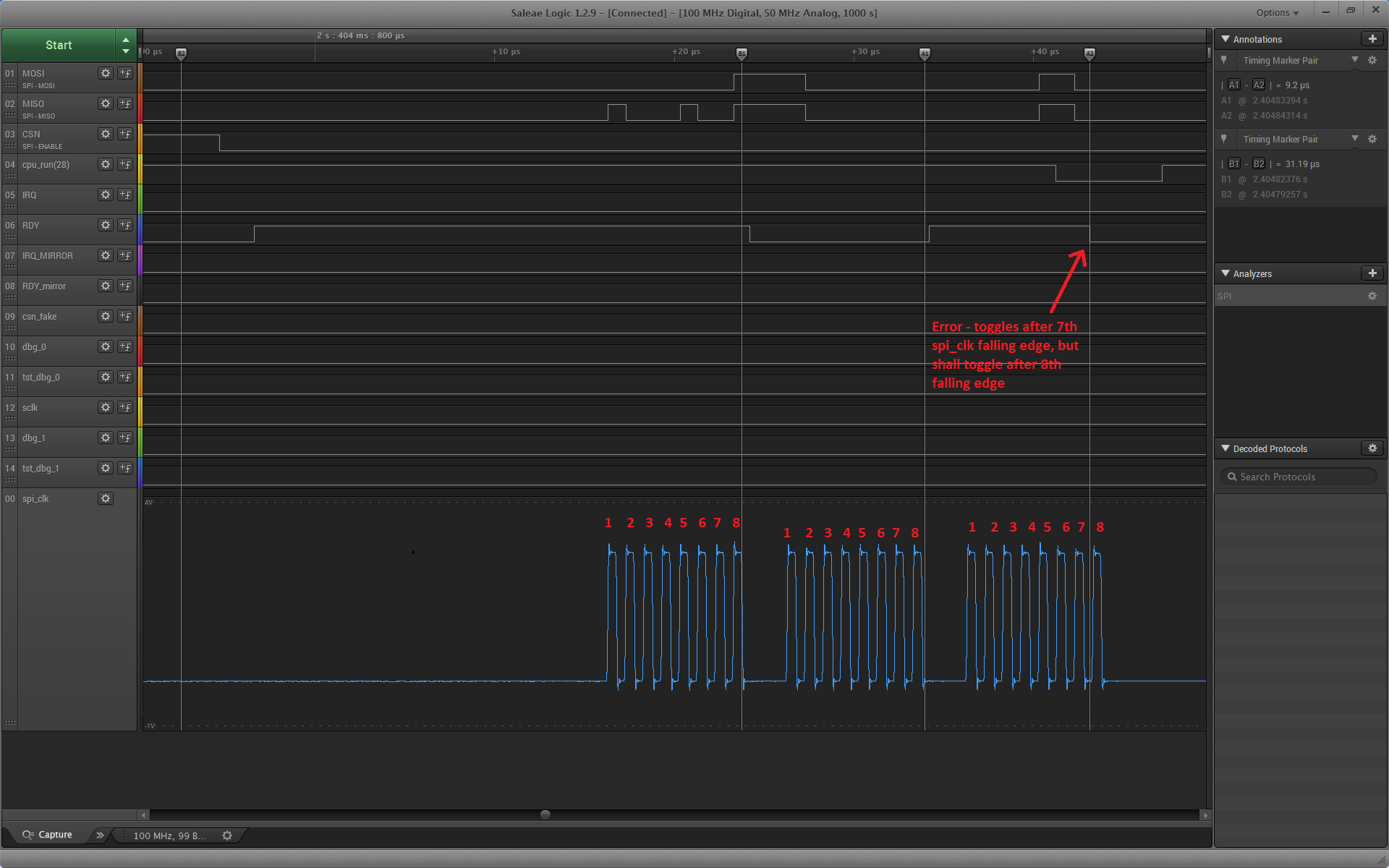
image description

[EDIT 25.1.2017] I got my hands on more pro oscilloscope than saleae. I captured problem on MSO7034A. It has 2 GPts/s. It shows there is no spike or noise: image description
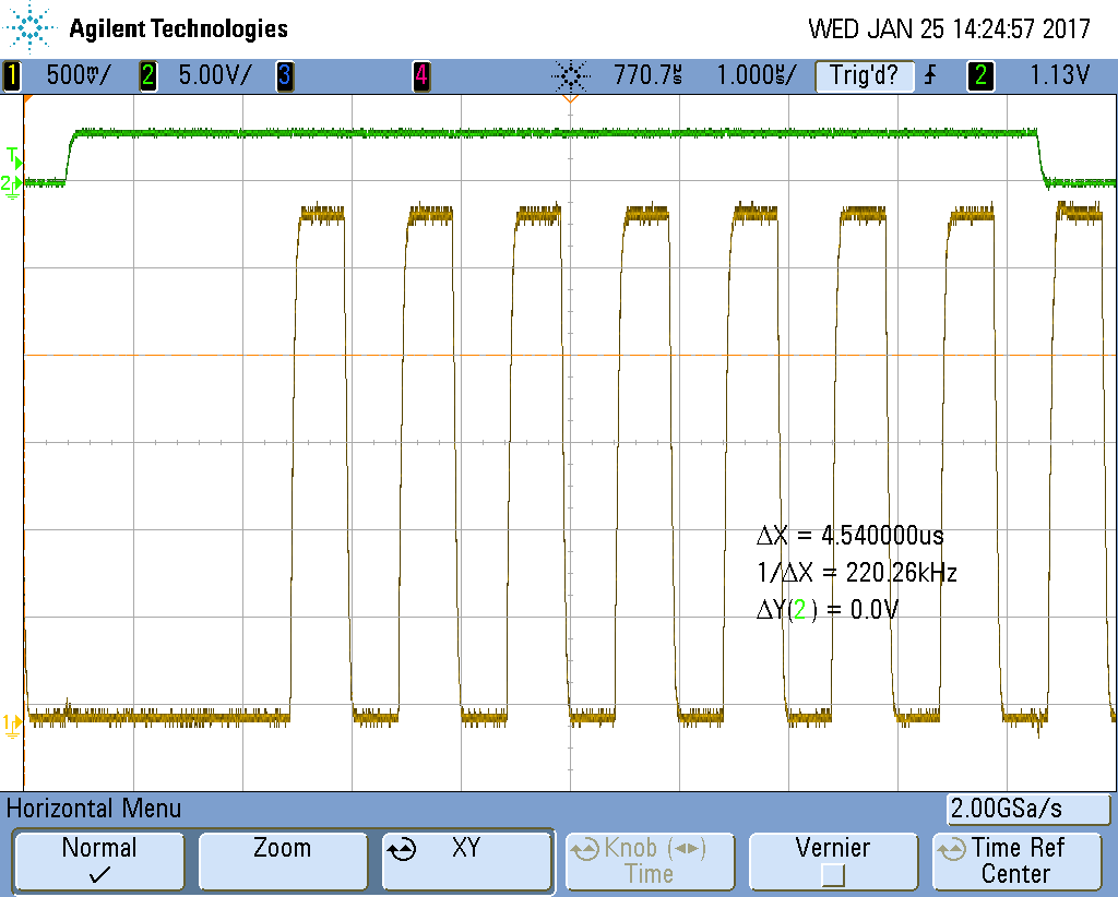
But in detail of edge there is some small noise: image description
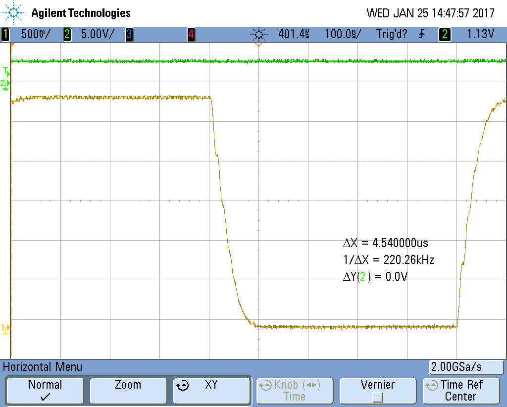
But nothing what a decent Schmidt trigger should not handle. Also I drive the signal from other nordic board, so either transmitter can not have fan out to 2 pin. Or receiver part is broken.

And to save one loop of suggestions - yes I already tried to modify nrf_drv_spi.c and chaged signal strength of SPI_CLK to NRF_GPIO->PIN_CNF[p_config->sck_pin] = ... GPIO_PIN_CNF_DRIVE_H0H1 ...; And no it did not fix the issue.

Could you please reproduce and give solution, other than decreasing SPI speed or using SW?

  • So GPIOTE IN event is configured for the same pin that is used SPI CLK? We normally do not recommend to use multiple peripherals on the same pin. Can you try to assign them to two different pins, connect them externally instead and see if the problem is still there?

  • What SPI Slave are you using ?

    Sounds like the PPI is being miss-triggered.

    Ole's answer sounds interesting, as I suspect you are not doing something that the hardware designers considered when they designed the PPI.

    As far as I can tell, you are running this the SPI at 8Mhz, did you try running it slower?

    Also. Does this problem occur if the logic analyser is not attached?

    Or is this peripheral on long wires etc.

    You may be able to resolve the problem by adding a filter that remove any high frequency noise from the clock line.

    Or as a last resort, you may need to write your own software "bit-banged" SPI in order to be able to use this device, or perhaps use an external divider IC to divide the clock by 8 in order to produce the toggling RDY signal.

  • I tired to use it also with other pin externally connected for Counter and it did not helped. BTW can you please point me where in documentation you recommend not to use same pin for more modules? I use NRF_SPIS0. Is there difference between SPIS modules? To me it seems that counter is miscounted rather than PPI would be mis-triggered (that I assume is consequence, not cause) My SPI_CLK is not 8MHz but 1MHz and no I can not go lower - system spec. The problem occurs also when logic analyser is not attached. Original wire was 55cm but problem stays if I use shorter wire 15cm. We are designing watch - it is problem for us to use external filter components - due to space. ARM chips often have internal debouncer if required for their counter.

  • We need very low power consumption - therefore we use as much sleep as possible. So SW implementation is problematic. I already have a SW design which works, but I tried to optimize with COUNTER+PPI.

    Can you reproduce the problem at your side? (note it requires more seconds to run to manifest the problem)

  • I cant see any noise on the signal from your pictures. But did it fail with the scope attached ?

    Btw. IMHO even 15 cm is a long signal path at 8mhz. Do you use a ribbon cable, as crosstalk can be a problem.

    I am not sure how you expect anyone to reproduce your problem as you have not shared your full source code or hardware designs.

    I recommend you contact Nordic for private support via their other portal, as this is a community forum and most of the people who answer questions ( me included) do not work for Nordic.

    Btw. A filter may only require one resistor and one capacitor, which would require very little space on your board, but it sounds like you dont have any analog design experience

Related