This post is older than 2 years and might not be relevant anymore
More Info: Consider searching for newer posts

nRF52832 SPI Master read results in "zeros"

Update 1/27/2016

  Just reviewing again the pins + schematic; I am using the following pins:

         SCK     P0.07
         CS       P0.08
         MOSI   P0.06

         MISO    P0.05/AIN3


  Looing at the MISO pin, it seems this is the only one that is "different" than the other 3 pins

  Is there something else that I need to do in order to use MISO pin on P0.05/AIN3; maybe because the pin can also be used as Analog Input ?


  Thanks.

Lee

Hi,

I am interfacing nRF52832 to an ADC chip; very simple SPI interface.

I am re-using the SPI examples from SDK 12.2.0; and the SPI runs without any problem.

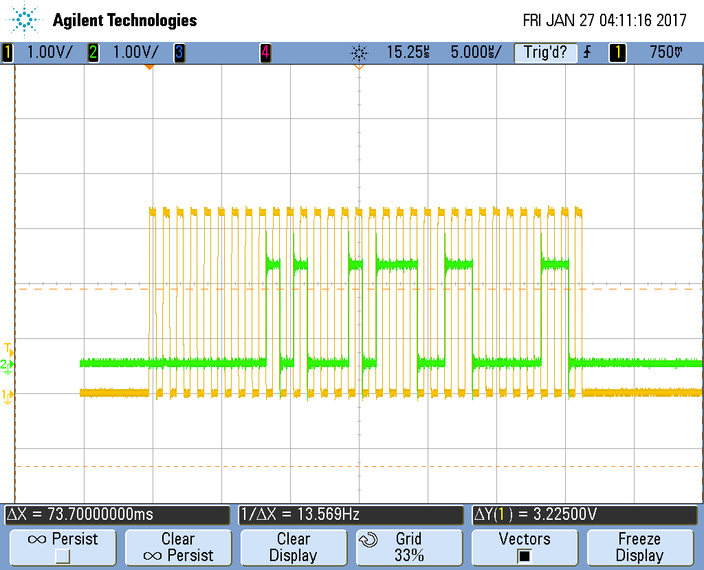
I can see the correct signals being generated on the SPI pins(CS, SCK, MOSI and MISO); in regards to MISO pins, I can see the ADC is sending the right bits(using a scope).

The SPI protocol requires: 1x TX byte and will receive 3 bytes of RX data.

On the scope, I can see a total of 32 SCK bits and the correct MISO data.

BUT in the output of the SPI interface APIs, the data read is all "zeros"; so 3 bytes of "0" values.

I have been double checking the codes and can't find any obvious error.

Any suggestion ?

I am attaching the scopes of the 2 pins: SCK and MISO.

Thanks for the help.

scope_3.png

Lee

  • You will need to post a snippet of your code, as you are almost certainly doing something wrong, as MISO clearly has data on it.

    I would also check which pin you have connected to MISO vs what you have configured in the code

  • As seen here, Pin P0.05 to P0.08 are by default used by the UART. Please check if you are using the UART module. If you are able to, you should also try switch to different pins to check if that solves the problem.

  • I am not using UART; so a straight copy of the SPI examples from SDK 12.2.0; I removed all calls to LED inits and replace the pin used from the ones used in the examples to my set of pins; noted that the SCK, CS and MOSI pins seems to work as I am getting expected MISO data(on the scopes) but not on internal registers

    It seems that somehow maybe I need to add another init for pin P0.05 as it is also can be used as Analog input; so far this seems the only thing that I can think of.

    I will look again at my codes and remove all relevant of any UART or any LOGs stuff

    Thanks, Lee

  • Commented UART, NRF_LOGs etc... from the sdk_config.h file; commented also GPIOTE option; still same issue ?

    Probably something obvious but at the moment, can't seem to figure out why I cam not getting data as shown on the MISO pin itself ?

    I am working on our own PCB board; so hard to change the pins assignment; try a few, but getting shorts in a few places; tiny pins and no test pads or vias to put test wires on.

    Thanks, Lee

  • I just tested the spi-master example on the nRF52-DK, with these settings:

    //APP_ERROR_CHECK(NRF_LOG_INIT(NULL));
    
    //NRF_LOG_INFO("SPI example\r\n");
    
    nrf_drv_spi_config_t spi_config = NRF_DRV_SPI_DEFAULT_CONFIG;
    spi_config.ss_pin   = 8;
    spi_config.miso_pin = 5;
    spi_config.mosi_pin = 6;
    spi_config.sck_pin  = 7;
    

    and it worked just fine.

    Also make sure that you are using the correct SPI mode. The default mode is "SCK active high, sample on leading edge of clock".

Related