Good day, I am using a USB to UART IC and it isn't working just because the nRF51822 Tx signal is inverted from this IC. There are some way to invert the UART signals?
Good day, I am using a USB to UART IC and it isn't working just because the nRF51822 Tx signal is inverted from this IC. There are some way to invert the UART signals?
Hmm, I'm not really sure where your problem is located.
We have to distinguish between Uart at TTL level (which is found directly at the pin of the nRF51822) and the Uart RS232 voltage level behind the driver (e.g. Max3222). They both are different in there voltage level and also inverted against each other (all signals: Rx, Tx, Rts, Cts …).
E.g. when the Uart is idle (not transfering data), we see a high level at the nRF51822's pin but a negative voltage behind the driver chip.
For me, as I'm using the nRFgo Starter Kit, RS232 communication was never such problem.
Thank you for the answer. Then I think there is some error on configurating my UART because the iddle level in the pin of the nRF51822 is low (0V) in my device.
You may show the code fragment of your uart configuration (using Sdk's simple_uart?) Even your Makefile is relevand (for something like BOARD := BOARD_NRF6310). Which nRF51822 hardware are you using (e.g. nRFgo or custom HW)? Have you tried to run the Sdk's uart example code?
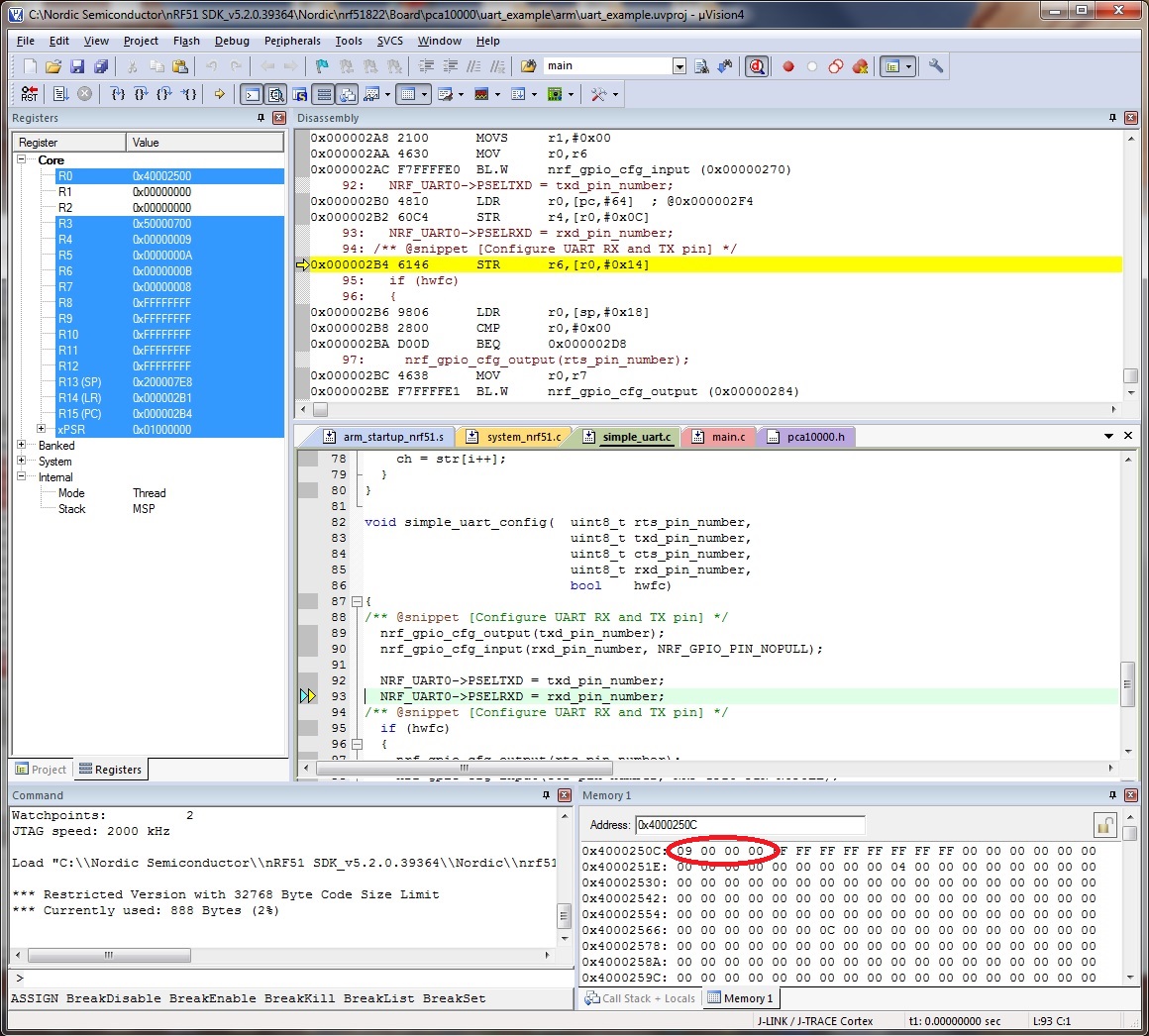
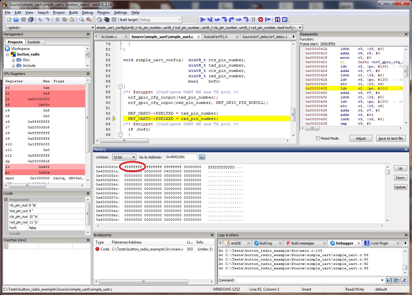
I am using a custom board with the Sdk's uart example code. It now worked with Keil IDE but I am trying to use EmIDE (which is free and size unlimited :-)). Somehow it isn't working properly. I see that the uart configuration in the memory 0x4000250C (and others) are not changing so it doesn't configure the TX/RX pins although it configures the RX/TX as input/output correctly..
Hi Joe. Attached are the print screens of what happen with emIDE (it didn't configure the "Pin select for TXD) and Keil (working) for the same source code. This configuration is at nRF51_Series_Reference_Manual_V2.1.pdf, page 163 (memory address 0x4000250C).

