
Hello,
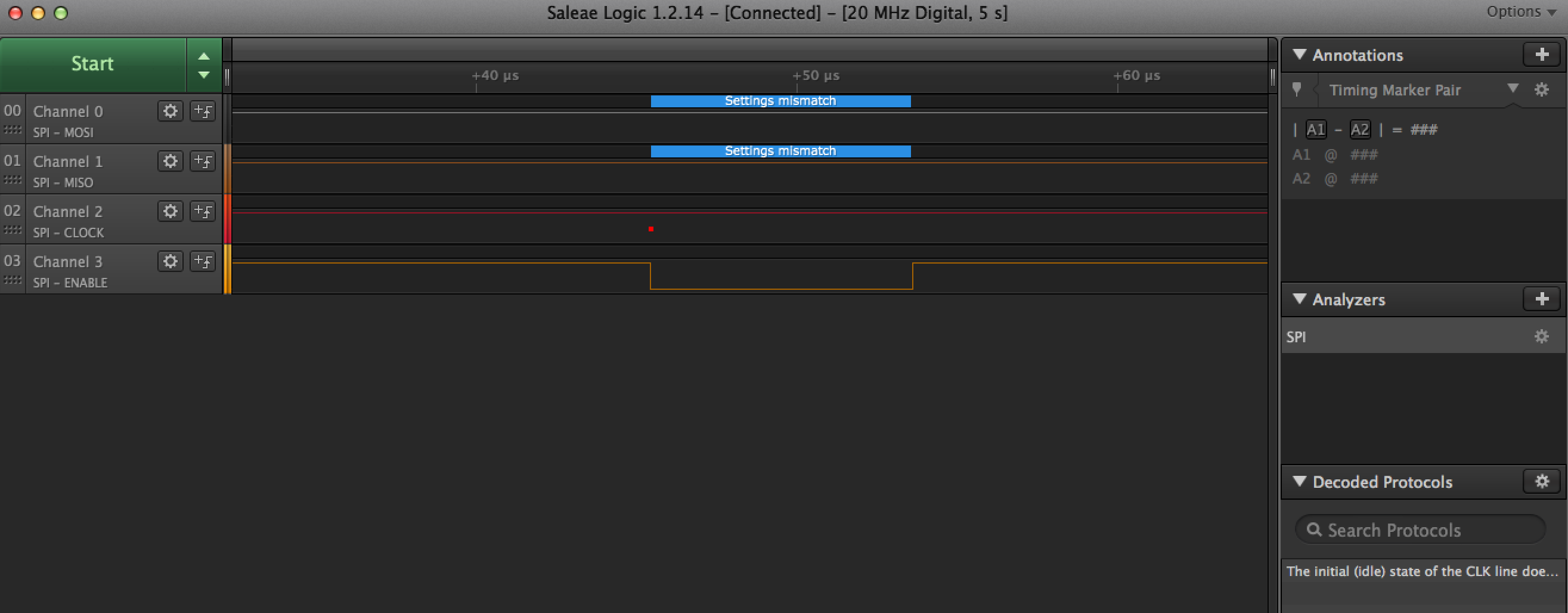
I am seeing something strange wrt to reassigning the NFC pins (9,10) on my Rigado BMD-300-EVAL using nRF SDK12.1 and gcc to build. I have two SPI based sensors on separate pins using two SPI interfaces (SPI0 and SPI1) for SPI1 we decided to use pins (10,9,11,7) for SCK, MOSI, MISO, and SS respectively. I followed the forums and discovered that setting the CONFIG_NFCT_PINS_AS_GPIOS C and ASM flag in my makefile should do the trick of freeing up those pins. However, after I do so I noticed that the CLK and MOSI pins are pegged high (as opposed to low like what happens in SPI0), and the CLK doesn't pulse when the SS goes active low. See attached logic analyzer image "NFCpins_reassigned.png". When I switch the SCK and MOSI to other pins such as 22, 23 SPI1 functions as normal and I see low SCK and MOSI and communication over the wire. See "using_pins_22_23.png". I wondering if anyone has seen this behavior before and can give guidance? We have made an architectural decision to use pins 9,10 for this SPI bus, and do not have the option to switch pins or combine to SPI0 at this point.
As workarounds I tried to force the pins 9,10 low using GPIOTE, before init of the SPI1 but that didn't have an effect, and the pins still remained high with no communication. Here is the code I used for that:
err_code = nrf_drv_gpiote_init(); //first make sure pins 9 and 10 are low nrf_drv_gpiote_out_config_t config = GPIOTE_CONFIG_OUT_SIMPLE(0); err_code = nrf_drv_gpiote_out_init(SPI1_SCK_PIN, &config); err_code = nrf_drv_gpiote_out_init(SPI1_MOSI_PIN, &config);
Lastly, I tried setting the SPI mode (NRF_DRV_SPI_MODE_0-3) to each of the four settings, and there is no change in behavior (no clk pulse nor communication).
Thanks for the time, and any help is greatly appreciated.
Josh
P.S - SPI0 functions perfectly in any SPI1 configuration so I don't think there is a contention issue between the two.

