This post is older than 2 years and might not be relevant anymore
More Info: Consider searching for newer posts

Key Pin for P3 (SWD) on PCA10004 and PCA10005 different

I just received my nrf51822 dev kit and noticed that the SWD debugging cable will only connect to the PCA10004. The PCA10005 that came with my kit has pin 2 missing, rather than pin 4 (on the PCA10004 board).

I've reviewed both sets of schematics and pc board layouts and, from what I can see, both boards should have the same missing key pin - pin 4 if I'm reading the numbering correctly. Either way, according to the ref docs, they should be the same and mine are not.

So unless I modify the connector, cable or manage some other mod I'm currently unable to use the PCA10005.

I can't imagine that the board was incorrectly assembled, though it's different than any of the reference docs I can find.

Thanks - Jeff

Addition:

http://i90.photobucket.com/albums/k278/alpineJeff/SWDP3_zps2d6cb811.png

Notice that pin 2 (2nd from the top right) is empty, while pin 4 is placed on bare board - no solder pad.

I'm about to unsolder, swap the pin, resolder - but I'd love some guidance on that approach first.

Thanks.

  • Hi Jeff,

    Unfortunately, it seems like there has been a mistake in the assembly of that particular module. The missing pin is pin3, which is normally ground. Since there is about 3 other GND pins on the connector, there is an easier fix than to flip the connector.

    I can see two alternatives:

    1. What you can do is to remove the small plastic "dummy pin" inside the SWD ribbon cable, then connect it to the board.
    2. Or simply cut the "floating" pin.

    I apologize for any inconvenience, and we will of course provide a replacement if the board is still not working.

    Best regards Håkon

  • Hello Håkon,

    Thanks for your reply.

    I spent the first 1/2 of yesterday with Keil, SEGGER and the PCA10004, since it's the only board I had that SWD debugger cable fit correctly.

    I was able to compile, connect and erase the chip, but no matter which example project I tried, or how many times I uninstalled and reinstalled ALL of the s/w bits, I couldn't get the debugger to successfully download to the chip's flash.

    As I mentioned above, it would erase, but I would always get the infamous:

    http://i1375.photobucket.com/albums/ag455/a-jeff/Cortex_zps9e297f90.png?t=1398352896

    
    Load "C:\\Keil_v5\\Nordic\\nrf51822\\Board\\nrf6310\\radio_test_example\\arm\\_build\\radio_test_example.axf" 
    Set JLink Project File to "C:\Keil_v5\Nordic\nrf51822\Board\nrf6310\radio_test_example\arm\JLinkSettings.ini"
    * JLink Info: Device "NRF51822_XXAA" selected (257 KB flash, 16 KB RAM).
     
    JLink info:
    ------------
    DLL: V4.84a, compiled Apr  4 2014 18:02:19
    Firmware: J-Link Lite-Cortex-M V8 compiled Aug 29 2012 15:24:23
    Hardware: V8.00
    S/N : 518005551 
    Feature(s) : GDB 
     
    * JLink Info: Found SWD-DP with ID 0x0BB11477
    * JLink Info: Found Cortex-M0 r0p0, Little endian.
    * JLink Info: FPUnit: 4 code (BP) slots and 0 literal slots
    ROMTableAddr = 0xE00FF003
     
    Target info:
    ------------
    Device: nRF51822_xxAA
    VTarget = 3.300V
    State of Pins: 
    TCK: 0, TDI: 0, TDO: 1, TMS: 1, TRES: 1, TRST: 1
    Hardware-Breakpoints: 4
    Software-Breakpoints: 8192
    Watchpoints:          2
    JTAG speed: 2000 kHz
     
    Erase Done.
    Programming Failed!
    Error: Flash Download failed  -  "Cortex-M0"


    So I was just about to give up on the whole Nordic approach, but decided to try the other radio - the PCA10005.., or, um, I mean PCA10006, and found that it's SWD cable wouldn't fit.

    So late last nite I decided to gently slide the sheath off of the P3 on the PCA10006, and with it came the one pin that wasn't soldered. I popped the pin out of the sheath, moved it down to the proper location, slid the sheath with the pin in its proper place back onto the board, a little touch of solder and the cable now fit. Yeah. But I still couldn't d/l any firmware.

    So my final attempt with the Nordic H/W was to try everything that I had spent my first 1/2 day on, using the PCA10004, with my newly repaired PCA10006.

    I had very very little hope of getting the firmware to download correctly after spending so much time the first 1/2 of the day on the other board.

    But with the very first try - it worked. I then got into my best single malt.

    So now I have one working radio, oh yeah, and 5 loose chips.

    Håkon, if you like to help me, if you could swap out the PCA10004 for a working version that would be MOST helpful. I'm 99% sure that it's a flash issue, not s/w, cabling, powersupply, etc., etc..

    That would be a most significant amount of help at this point in my evaluation.

    Let me know if that's at all possible.

    Warm regards, and thanks again for your help!

    Jeff

  • Hi Jeff,

    I believe your debugger interface is working properly, as the SWD connection is successful. The reason why you're seeing a "flash download failed" is most likely because you have the Softdevice already loaded into the flash.

    If you open the cmd line, write "nrfjprog --eraseall", it will leave the nRF51-chip completely blank, so that you can load peripheral project w/o changing settings. Could you try this before getting a new module?

    Best regards Håkon

  • Hey Håkon,

    Using the command line "nrfjprog --eraseall" did the trick. Thanks.

    I tried a subsequent flash::erase using Keil which failed. Even just a subsequent flash::download into I get the Cortex-M0 error.

    It appears that I need to use the cmdline tool every time I want to update the flash? The integrated Keil tool does not work, is that correct?

  • Hi Jeff,

    If you have the S110 softdevice present in flash,it claims flash area 0 - 0x14000, and you cannot overwrite or erase single pages in this area. If you application tries to write to this address area, you will get that specific error from Keil/Segger.

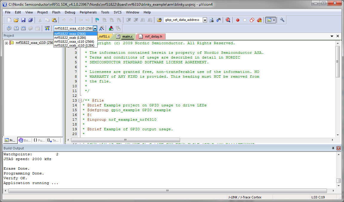
    If you have S110 present on your device, you could change the project as shown in the attached image. The project will then be setup with the proper flash/RAM offset.

    I see that you have a new version of the segger drivers installed. What version of Keil are you using?

    Best regards Håkon

    keil_s110_dropdown.png

Related