Hi,
to investigate a timing problem in my Bluetooth stack, I've hard wired the Radio ADDRESS and END events to a GPIO pin using the PPI. The ADDRESS event is used to toggle the pin to high, and the END event is used to toggle the pin back to low.
Now I have a sequence that I do not fully understand. Maybe someone here can help me to find, where I'm wrong: The stack sends a 47 octet long advertising PDU (including preamble, access address, payload and CRC). As the ADDRESS event happens right after sending the access address, I expect the pin to go high after the first 5 octets (preamble and access address) and to remain high for the next following 42 octets. As one bit over the air lasts exactly 1µs, the the pin should be high for exactly 4281µs == 336µs. I measure 337.1µs, so that's quite close to it.
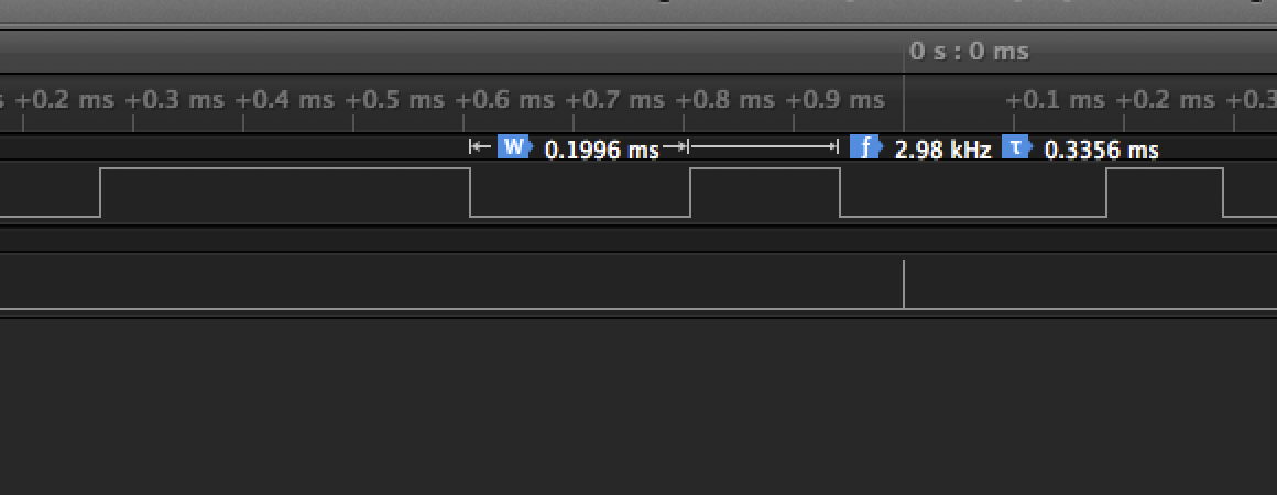
Now, according to the core specification, a scan request has to be send 150µs after the advertisement (+-2µs). During the receiving of this scan request the ADDRESS event should happen exactly 40µs (5 octets for preamble and access address) after the beginning of the PDU and as the PDU should have been send out 150µs after the last END event, I should find the next ADDRESS event 150+40µs later. BUT: I'm measuring always 200µs!
So one reason could be that the scan request is indeed send out 160µs after the advertising PDU, but: the Nordic Sniffer is telling me, that it is 150µs and I measure the same 160µs when I use my MacBook, my iPhone or an Nexus phone to generate the scan request. So I think it's most likely that there is a mistake in my reasoning.
Edit: This is the code to configure PPI and GPIOTE:
        NRF_GPIOTE->CONFIG[ 0 ] =
            ( GPIOTE_CONFIG_MODE_Task << GPIOTE_CONFIG_MODE_Pos ) |
            ( debug_pin_transmit << GPIOTE_CONFIG_PSEL_Pos ) |
            ( GPIOTE_CONFIG_POLARITY_Toggle << GPIOTE_CONFIG_POLARITY_Pos ) |
            ( GPIOTE_CONFIG_OUTINIT_Low << GPIOTE_CONFIG_OUTINIT_Pos );

        NRF_PPI->CH[ 0 ].EEP = reinterpret_cast< std::uint32_t >( &NRF_RADIO->EVENTS_ADDRESS );
        NRF_PPI->CH[ 0 ].TEP = reinterpret_cast< std::uint32_t >( &NRF_GPIOTE->TASKS_OUT[ 0 ] );

        NRF_PPI->CH[ 1 ].EEP = reinterpret_cast< std::uint32_t >( &NRF_RADIO->EVENTS_END );
        NRF_PPI->CH[ 1 ].TEP = reinterpret_cast< std::uint32_t >( &NRF_GPIOTE->TASKS_OUT[ 0 ] );

        NRF_PPI->CHENSET = 0x3;