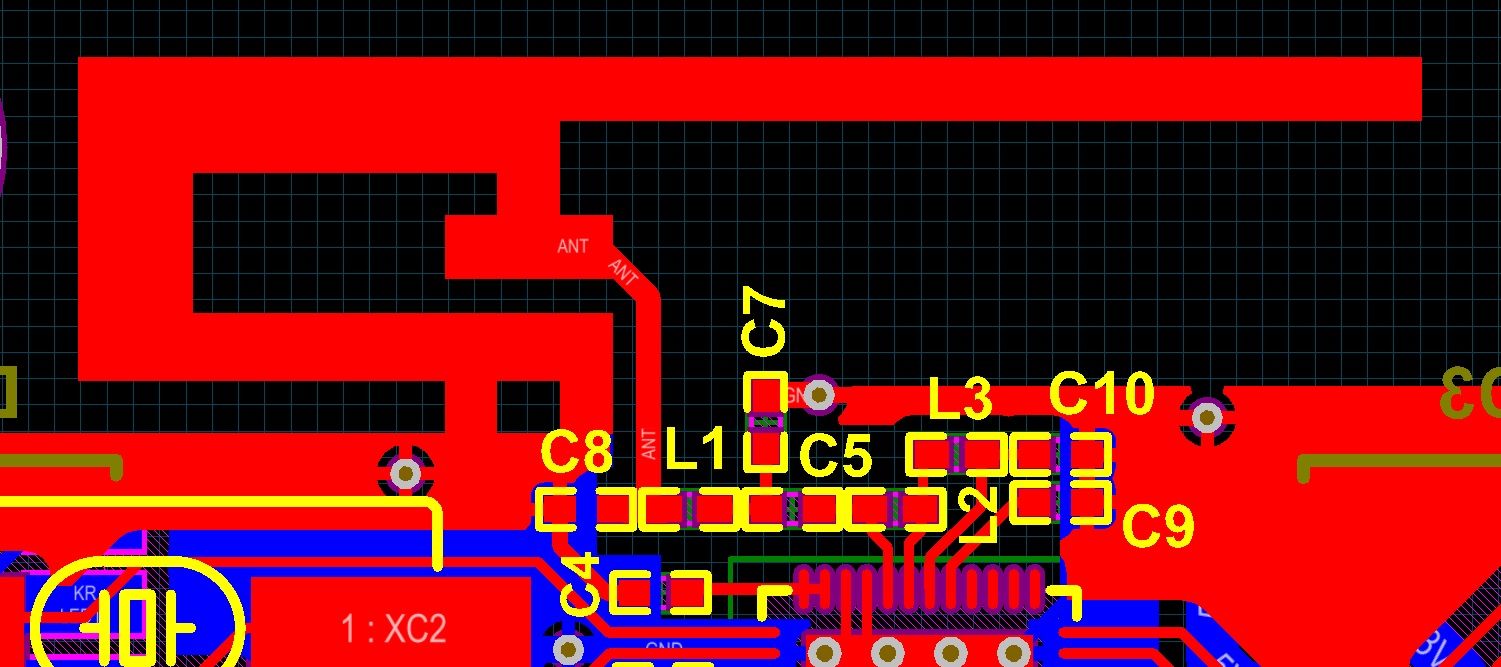
Hi, I have used this antenna for my nRF51 layout, but it seems that the device is using very high currents! like in order of 200mA, I just wanted to know if this is because the antenna is a short circuit at DC or I have done something else wrong!
Ah... That would be a problem !
Not if, as research indicates, the stub end of the F antenna is meant to be grounded. Still don't know how that works but it appears to be correct.
OK. Depending on the type of antenna, I agree it could be connected to GND. and not be a electrical short to gnd.
But perhaps the autorouter PCB package decided to directly connect it to GND.
I would have thought, best practice would be to show the antenna as an inductor to GND if thats what is physically required, and then create a PCB symbol which is the physical shape of this inductor
This would get rid of the DRC errors without accidental shorting both ends of C8 directly to GND
@myjtag: It is possible to use an inverted F design, but we generally recommend following our reference designs, i.e. using either quarter wave antenna or a meander antenna. Its hard to say what might be the issue without seeing the entire layout , but 200mA sound very very high. Could you upload the gerbers?
(not knowing how an F-Antenna is supposed to work...) if you can afford to sacrifice a PCB: remove the antenna with a cutter and solder a coaxial cable with a known, good antenna. Is the power consumption now as expected?