Hi
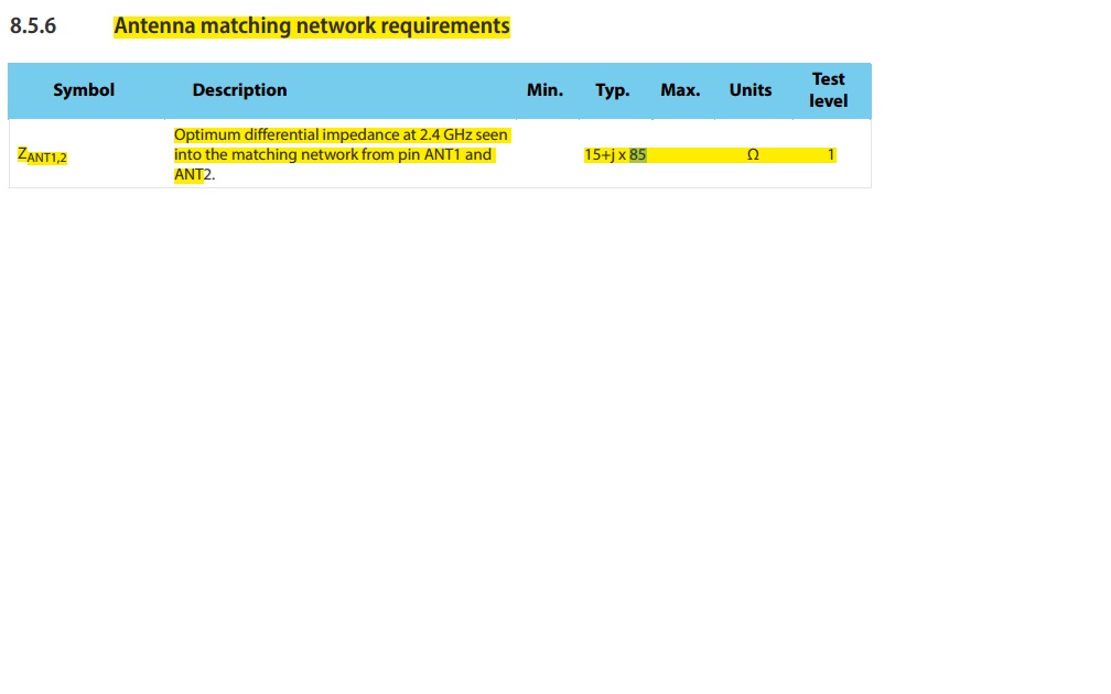
I got some questions about the RF part of the ref schematic. 1, why the bias voltage for ANT1 anf ANT2 are not the same since they are differential lines? 2, what's the impedance from L1 to ANT1 and ANT2? Is it 15+85j? How am i gonna tell the PCB manufacturer to control the impedance?
BR ealon