
Hi,
I am using the nRF52832 on a custom PCB and I am interfacing it with a flash memory chip through SPI.
I am testing the SPI communication using the spi example (nRF52 SDK 14.2.0\examples\peripheral\spi).
Using an oscilloscope I can see that each transmitted byte (from m_tx_buf) is followed by 24 clock cycles during which the MOSI line is low.
I would like to know how to transmit continuously, without these 24 additional clock cycles.
I have tried to feed nrf_drv_spi_transfer with a NULL pointer for the rx buffer, so that no rx is expected, but nothing changed.
Here is main.c:
#include "nrf_drv_spi.h"
#include "app_util_platform.h"
#include "nrf_gpio.h"
#include "nrf_delay.h"
#include "boards.h"
#include "app_error.h"
#include <string.h>
#include "nrf_log.h"
#include "nrf_log_ctrl.h"
#include "nrf_log_default_backends.h"

#define SPI_INSTANCE  0 /**< SPI instance index. */
static const nrf_drv_spi_t spi = NRF_DRV_SPI_INSTANCE(SPI_INSTANCE);  /**< SPI instance. */
static volatile bool spi_xfer_done;  /**< Flag used to indicate that SPI instance completed the transfer. */

static int       m_tx_buf[] = {170, 170};                /**< TX buffer. */
static uint8_t       m_rx_buf[1];                        /**< RX buffer. */
static const uint8_t m_length = sizeof(m_tx_buf);        /**< Transfer length. */
static const uint8_t m_rx_length = sizeof(m_rx_buf);

/**
 * @brief SPI user event handler.
 * @param event
 */
void spi_event_handler(nrf_drv_spi_evt_t const * p_event,
                       void *                    p_context)
{
    spi_xfer_done = true;
    NRF_LOG_INFO("Transfer completed.");
    if (m_rx_buf[0] != 0)
    {
        NRF_LOG_INFO(" Received:");
        NRF_LOG_HEXDUMP_INFO(m_rx_buf, strlen((const char *)m_rx_buf));
    }
}

int main(void)
{
    bsp_board_leds_init();

    APP_ERROR_CHECK(NRF_LOG_INIT(NULL));
    NRF_LOG_DEFAULT_BACKENDS_INIT();

    NRF_LOG_INFO("SPI example.");

    nrf_drv_spi_config_t spi_config = NRF_DRV_SPI_DEFAULT_CONFIG;
    spi_config.ss_pin   = SPIS_CSN_PIN;
    spi_config.miso_pin = SPIS_MISO_PIN;
    spi_config.mosi_pin = SPIS_MOSI_PIN;
    spi_config.sck_pin  = SPIS_SCK_PIN;
    APP_ERROR_CHECK(nrf_drv_spi_init(&spi, &spi_config, spi_event_handler, NULL));

  while (1)
    {

        // Reset rx buffer and transfer done flag
        // memset(m_rx_buf, 0,  m_rx_length);
        spi_xfer_done = false;
        APP_ERROR_CHECK(nrf_drv_spi_transfer(&spi, m_tx_buf,  m_length, NULL,  0));

        while (!spi_xfer_done)
        {
            __WFE();
        }

        NRF_LOG_FLUSH();


        bsp_board_led_invert(BSP_BOARD_LED_0);
        nrf_delay_ms(20);

     }
}
And here are the oscilloscope traces (the yellow one is MOSI and the green one is SCK):
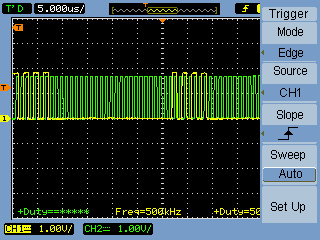
As mentioned above, the transmitted byte 10101010 is followed by 24 clock cycles where MOSI is low.
Thank you in advance for your help.

