This post is older than 2 years and might not be relevant anymore
More Info: Consider searching for newer posts

nRF52840 PDK to external board programming

I'm using the P20 connectors in nRF52 PDK to flash my custom nRF52832 board.

The connections are like this:

SWDIO ----> SWDIO

SWDCLK ---->SWDCLK

VTG ------> VDD

GND DETECT, GND ----> GND

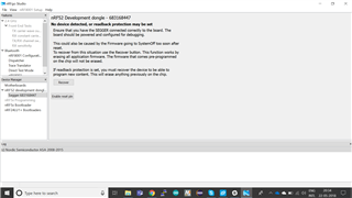
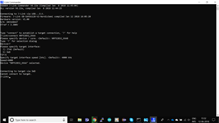
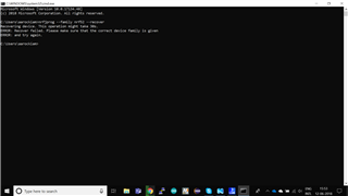
I've powered up the custom board externally. I'll attach a screenshot of the error I'm receiving. Is the connections I've given correct? or Is there any workarounds for solving this problem. nrfjprog is also throwing an error as JLINKARM_DLL_ERROR. 

  • If we short the VDD_nRF and VTG pins, where should the custom boards' VDD be connected? Should the board be powered separately?

    Thanks

    -vivenkat

    Edit 1: My connections are as follows:

    On P20,
    VDD_nRF and VTG are shorted
    VDD is used to power the custom Nordic board

    SWDIO and SWDCLK in nRF52 DK to SWDIO and SWDCLK on the custom Nordic board

    One of the GND pins from the DK to the custom board.

    I have the same error as Labuka. Any help would be gladly appreciated!

    -vivenkat

  • Hi,


    If we short the VDD_nRF and VTG pins, where should the custom boards' VDD be connected? Should the board be powered separately?

    When shorting VTG->VDD_NRF (or pin VDD), you tell the board to use P20 as the target debug. Your external board, connected to P20 (1x8 header), should still be powered. I recommend powering your external board with either "VDD" or "VDD_NRF" from the nRF5x-DK. This is to ensure that the voltage is equal on both the debugger and your custom board.


    If you still have issues connecting to your board, please check with both nrfjprog and JLink Commander and post logs from both programs.


    Best regards,

    Håkon


  • Hi,

    I gave the connections exactly as you described but still I'm facing the same issues. I'll post the logs for reference.

  • Could you check the current consumption of your external board?

    You haven't cut SB9 on a previous occasion and not remembered to place a jumper cable on the "nRF current measurement" header?


    Best regards,

    Håkon 

  • "When shorting VTG->VDD_NRF (or pin VDD), you tell the board to use P20 as the target debug. Your external board, connected to P20 (1x8 header), should still be powered" - where should this command be given ?

    On my DC power supply, the current reading is around 94 mA. I have a pca10040 Atmel IC and I am using it to program a nRF52810. The display on my JLink commander and nRFgo studio is the same what Labuka posted.

    Thanks very much for your reply!

    -vivenkat  

Related