This post is older than 2 years and might not be relevant anymore
More Info: Consider searching for newer posts

Radiated Emissions failure (receiver spurious emissions test)

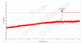
We are currently going through certification and have had an interesting failure during radiated emissions.  When in normal transceiver mode, all is well, but when we put the device into a special receiver only mode using the Wirepas tool then we fail at the second harmonic of 4.8GHz even though there are no emissions at 2.4GHz.  Very odd. 

I would have thought that, if anything, we would fail a transmitter test rather than a receiver test.  Could the emissions be coming from the receiver local oscillator?  What would you suggest to try and fix it?

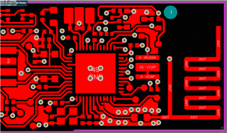
Incidentally, we are using a pretty standard meandering inverted F PCB trace antenna with parallel cap and series inductor. 

  • FormerMember
    0 FormerMember

    Yes, that emission is from the RX LO, and most likely, it's related to errata 138. The fix is to either ground P0.25 and P0.26 if the pins are not used, or place a 12 pF capacitor near the pin to ground on both pins. (See the reference layout.)

  • Hi Kristin,

    We encoutered the same issue (I made a private ticket where I shared my design files). We use the CIAA package and there is no updated reference layout for this one, only for QFAX. The P0.25 and P0.26 are unused in the final product, but by coincidence we used these pins for the UART connection for DTM mode. I was wondering, since we don't use these pins and I would like to find a fix which does not mean another iteration on the PCB, if it is sufficient to ground the pins by setting an internal pull-down? Or is it required to have a direct ground connection?

    Best regards,

    Wout

  • FormerMember
    0 FormerMember

    QFAX: Unfortunately, it is no sufficient to configure the pins as GPIO and set internal pull-down, the pins has to physically be grounded or "grounded" via a capacitor.

    CIAA: This is normally not a problem for the CSP variant. What is the case number of the private case?

  • Thank you very much for your help. It sounds like this problem is already known, so we will try it and let you know the result. 

    Unlucky for us we have assigned both of these pins, but that is something that we can handle. 

    Thanks

    Mike

  • Hello Kristin, 

    We tested the solution today and the result was unsuccessful.  Both pins P0.25 and P0.26 are currently allocated in our design, so we put 12pf caps from these pins to ground and saw no change in the 4.8GHz emission.  We then connected these pins to ground and saw no improvement to the emission. 

    We used a near field sniffer probe for the test and it was hard to pinpoint where the source was.  We disconnected the antenna by removing the series L and that made no difference, so I presume is not coming from the antenna. 

    I have pasted an image of the top layer of our four later board for your reference. 

    This product is going into mass production in a few months time so we are really needing help to fix this issue.  Any advice you can offer is appreciated. 

    Regards

    Mike

Related