This post is older than 2 years and might not be relevant anymore
More Info: Consider searching for newer posts

initial pulse while starting a PWM application

Hi,

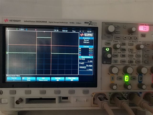
A short summary, while using the app_PWM on our application I noticed an initial pulse on the PWM pin, its a 3V 1ms pulse that happens about 1 sec after powering on the nRF52832... 

The PWM configuration and initializations code is quite standard:

int main(void)

{
    initialize();
    // Initializing the PWM instance in main() function
    ret_code_t err_code;
    app_pwm_config_t pwm1_cfg = APP_PWM_DEFAULT_CONFIG_1CH(1000L, ON_OFF_LED);
    pwm1_cfg.pin_polarity[1] = APP_PWM_POLARITY_ACTIVE_LOW;
    err_code = app_pwm_init(&PWM1,&pwm1_cfg,pwm_ready_callback);
    app_pwm_enable(&PWM1);
    while ( app_pwm_channel_duty_set(&PWM1, 0, MIN_LIGHT_INTENSITY) == NRF_ERROR_BUSY);
    APP_ERROR_CHECK(err_code);

    execution_start(start);

Is there something I need to configure / disable / initialize on the PWM or the Startup sequence so I don't get this initial pulse? 

  • Hi,

    There is a problem with the code you described in your last post, which is that you should call app_pwm_enable() before you call app_pwm_channel_duty_set(). Calling it the other way around causes the library to misbehave. This is unfortunately not documented as far as I can see and not obvious. There is also a problem that you set the duty cycle to 1000, which is not in the valid range (0 - 100).

    You could update the code to be like this:

    app_pwm_config_t pwm1_cfg = APP_PWM_DEFAULT_CONFIG_1CH(1000L, ON_OFF_LED);
    pwm1_cfg.pin_polarity[0] = APP_PWM_POLARITY_ACTIVE_LOW;
    err_code = app_pwm_init(&PWM1,&pwm1_cfg,pwm_ready_callback);
    app_pwm_enable(&PWM1);
    while ( app_pwm_channel_duty_set(&PWM1, 0, 100) == NRF_ERROR_BUSY);

    In this case the pin state will be like the following:

    • After reset before the pin is configured it will be the default state (disconnected input) = high impedance.
    • After executing line 3 the pin will be configured as an output pin and set to the non-active state - high in this case.
    • After executing line with the duty cycle is set to 100%, the pin should stay in the active state - low in this case.

    So in this case you get the 1 ms pulse you have described and that is expected.

    If you do the trick I mentioned you would have something like this instead. In that case you will not see any pulse:

    app_pwm_config_t pwm1_cfg = APP_PWM_DEFAULT_CONFIG_1CH(1000L, ON_OFF_LED);
    pwm1_cfg.pin_polarity[0] = APP_PWM_POLARITY_ACTIVE_HIGH;
    err_code = app_pwm_init(&PWM1,&pwm1_cfg,pwm_ready_callback);
    app_pwm_enable(&PWM1);
    while ( app_pwm_channel_duty_set(&PWM1, 0, 100-100) == NRF_ERROR_BUSY);

  • Hi Einar,

    Thanks for the info, very useful indeed, and just to clarify, I used 1000 because I also edited the PWM driver library and set the range 0 to 1000 to have better control of the PWM on a logarithmic scale thats quite important in lighting, actually I might even go to 0 to 10000... in lighting the 0% to 10% its quite important and difficult to manage due to the non linear response from our eyes...

Related