This post is older than 2 years and might not be relevant anymore
More Info: Consider searching for newer posts

SPI communication problem

Hello Slight smile

I'm using NRF52 PCA10040 board., SDK 15.2 libraries with GNU ARM GCC and Eclipse as an IDE developing FW on Windows10 x64.

I have been facing a problem trying to service external SPI flash memory (AT25SF041, but not only - you can read about it further). I'm not able to read memory ID registers. More precisely I got incorrect response from the memory.

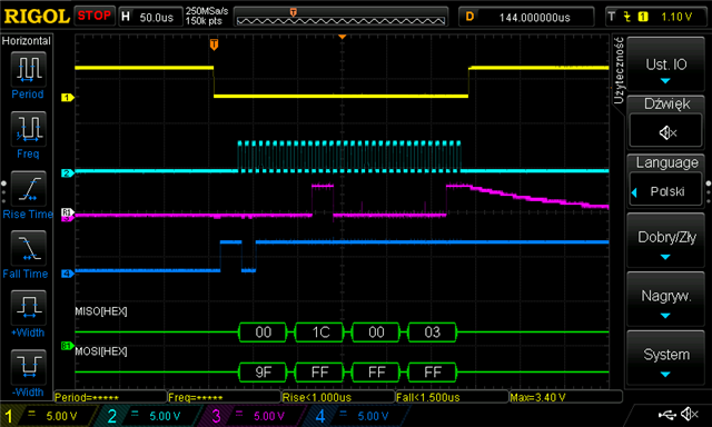
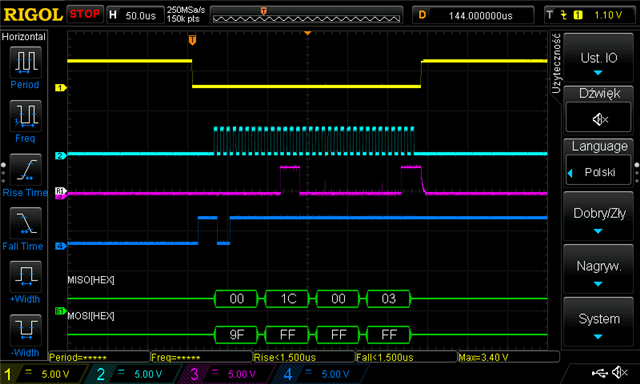
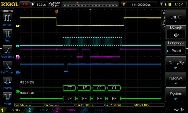
I was trying few memory chips from different vendors with the same result. I have no such a problem using STM32L0 MCU. What is more interesting, I have been investigating SPI communication at electric signal level using DSO and both communication (using NRF52 and STm32) looks exactly the same with the difference that memory responds to ID request got from SMT32 with appropriate device ID data but on NRF52 request it sends incorrect response.

Has anyone ever met such a strange problem?

Here is the low-level code I've written for AT25SF041 driver:

#include "nrf_gpio.h"
#include "nrfx_spi.h"
 
#include "logger.h"
 
#define CS_PIN          28
#define SCK_PIN         29
#define MISO_PIN        30
#define MOSI_PIN        31
 
 
static const nrfx_spi_t _xSpiHandler = NRFX_SPI_INSTANCE(0);
static nrfx_spi_config_t _xSpiConfig = NRFX_SPI_DEFAULT_CONFIG;
 
static uint8_t _bIsInitialized = 0;
static volatile uint8_t _bTransferFinished;
 
static void prvvSpiEventHandler(nrfx_spi_evt_t const* aEvent, void* aContext)
{
    _bTransferFinished = 1;
}
 
void AT25SF041_vInitializeLL()
{
    if (_bIsInitialized)
    {
        return;
    }
 
    /** Set SPI pins n the configuration object and initialize interface. */
    _xSpiConfig.miso_pin = MISO_PIN;
    _xSpiConfig.mosi_pin = MOSI_PIN;
    _xSpiConfig.sck_pin = SCK_PIN;
    _xSpiConfig.ss_pin = NRFX_SPI_PIN_NOT_USED;
    _xSpiConfig.frequency = NRF_SPI_FREQ_125K ;
    _xSpiConfig.mode = NRF_SPI_MODE_0;
    nrfx_spi_init(&_xSpiHandler, &_xSpiConfig, &prvvSpiEventHandler, NULL);
 
    /** Prepare CS pin and set its state to HGH. */
    nrf_gpio_cfg_output(CS_PIN);
    nrf_gpio_pin_set(CS_PIN);
 
    _bIsInitialized = 1;
}
 
void AT25SF041_vSetCSActiveLL()
{
    nrf_gpio_pin_clear(CS_PIN);
}
 
void AT25SF041_vSetCSInactiveLL()
{
    nrf_gpio_pin_set(CS_PIN);
}
 
int8_t AT25SF041_bXferBytesLL(uint8_t* aTxBuf, uint8_t aTxLen, uint8_t* aRxBuf, uint8_t aRxLen)
{
    nrfx_spi_xfer_desc_t xferDesc = NRFX_SPI_XFER_TRX(aTxBuf, aTxLen, aRxBuf, aRxLen);
 
    AT25SF041_vSetCSActiveLL();
 
    _bTransferFinished = 0;
 
    nrfx_err_t error = nrfx_spi_xfer(&_xSpiHandler, &xferDesc, 0);
    if (error != NRFX_SUCCESS)
    {
        return -1;
    }
 
    while (!_bTransferFinished)
    {
    }
 
    AT25SF041_vSetCSInactiveLL();
 
    return 0;
}

  • I would try increasing the SPI clock frequency to at least 1MHz and boosting the drive of the three output signals to the flash; later on you can always investigate reducing drive strength again. Insert this after configuring SPI:

       // High power output pins
       nrf_gpio_cfg(CS_PIN,
                    NRF_GPIO_PIN_DIR_OUTPUT,
                    NRF_GPIO_PIN_INPUT_DISCONNECT,
                    NRF_GPIO_PIN_NOPULL,
                    NRF_GPIO_PIN_H0H1,       // Require High Drive high and low level
                    NRF_GPIO_PIN_NOSENSE);
       nrf_gpio_cfg(SCK_PIN,
                    NRF_GPIO_PIN_DIR_OUTPUT,
                    NRF_GPIO_PIN_INPUT_DISCONNECT,
                    NRF_GPIO_PIN_NOPULL,
                    NRF_GPIO_PIN_H0H1,       // Require High Drive high and low level
                    NRF_GPIO_PIN_NOSENSE);
       nrf_gpio_cfg(MOSI_PIN,
                    NRF_GPIO_PIN_DIR_OUTPUT,
                    NRF_GPIO_PIN_INPUT_DISCONNECT,
                    NRF_GPIO_PIN_NOPULL,
                    NRF_GPIO_PIN_H0H1,       // Require High Drive high and low level
                    NRF_GPIO_PIN_NOSENSE);
    

    I would also reconsider your pin choice, especially when using much higher clock speeds:

    4.3.1 GPIO located near the radio
    Radio performance parameters, such as sensitivity, may be affected by high frequency digital I/O with large sink/source current close to the Radio power supply and antenna pins.
    Table 5: GPIO recommended usage for QFN48 package on page 17 and Table 6: GPIO recommended usage for WLCSP package on page 17 identify some GPIO that have recommended usage guidelines to maximize radio performance in an application.
    Table 5: GPIO recommended usage for QFN48 package
    Pin GPIO
    27 P0.22
    28 P0.23
    29 P0.24
    37 P0.25
    38 P0.26
    39 P0.27
    40 P0.28
    41 P0.29
    42 P0.30
    43 P0.31

  • I see that you are configuring the SPI freq at 125K.  This will not work for many Flash devices.  Min would be 1M but some flash would need 4M.  So try at 4M first to see if you can read the ID.

  • Hi :)
    Thank you for your input. The problem is that I can communicate with the device using exactly the same SPI configuration when using STM32 as a host controller. I know that 125K is a little bit slow and I do not plan to use it in production environment (it will be 1M at least). I just set 125K to have a nice looking clock signal, thus show communication on DSO clearly.

  • The clock is always nice sine it is generated by the master.  Yet, I have encountered many flash chips that do respond well under 1M.  Don' t remember which one.

  • Sorry for late answer, I wasn't at office last two days. I tested all options but communication is still wrong. The only change is the response, but it might be connected to the fact that I switched tfrom nrfx_spi to nrfx_spim driver. Please take a look at screenshots below.

    1. With NRF_GPIO_PIN_NOPULL


    2. With NRF_GPIO_PIN_PULLDOWN

    3. With NRF_GPIO_PIN_PULLUP

Related