This post is older than 2 years and might not be relevant anymore
More Info: Consider searching for newer posts

Power measurement with external power supply

Hello everyone,

I am trying to measure the current being consumed by nrf52840 using an external power supply.

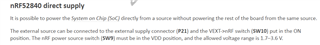
Setup: I have connected 3.3V DC power supply to connector P21 and switch 10 is in ON position and switch 9 is in VDD position. As specified in the picture below. 

However, the board is not running with this setup.

As mentioned in the second screenshot, supply VDD domain from a different source, I tried connecting USB to power the remaining board. But it does not work.

Kindly help me understand how I can power the rest of the board? If I have to power the rest of the board with USB what extra changes do I have to make on the board?

Regards,

Sameer 

  • Hi, seems like your setup is correct. When you say "the board is not running" with this setup, do you mean the nRF52 chip or the board itself? What do you need to run on the board? So the point of SW10 is to bypass the components on the DK powering the nRF52 chip directly. You should also set SW6 to nRF ONLY. Now you can measure current. If you need to use the JLink on the DK you need to set SW10 back to the OFF position.

    It's true that USB has to be connected on order to power "the rest" of the board. This is so that the components are not floating and not interfering with the operation of the nRF52 (more specifically the reset and SWD lines).

  • Thanks Stian,

    I am running one simple application where client is periodically sending few packets to server. The boards are provisioned and configured. So when I connect the external power supply with all other right settings (as mentioned above) on the client board, the server should receive the packets (I am powering the client with external supply and server is still powered through USB). But server doesn't receive any packet. So I believe the board is not running. What can be wrong here? 

    Can we also power the board with Vin pin on the P20? 

    Regards,

    Sameer 

  • Have you enabled UART, UART logging, RTT logging or similar, or are you using any other peripherals on the board, like the nRF USB port, or external flash?

    Is your code based on any of the examples from the SDK? If so, I can try it out here and see what happens.

  • The application is based on light switch example. I have just added a timer to periodically send a message. As soon as the client is powered on it starts sending packets to the server. No other changes on the application. 

    Kindly try running this. If you can share some info on, how can I power the rest of the board along with external supply 3.3v through P21 (with SW10 on, SW9 at Vdd and sw6 at nrf_only)? It will be helpful.

    Regards,

    Sameer  

  • Hello Sitan,

    Did you try running this setup?

    Please let me know if any additional info is required.

    Regards,

    Sameer 

Related