This post is older than 2 years and might not be relevant anymore
More Info: Consider searching for newer posts

SPI Communication Problems Concerning nRF52840

Now there is a project, nrf52840 uses SPI to communicate with other microcontrollers. Data is currently available, but it is suspected that each packet lacks a second byte. The corresponding modification of SPI mode eliminates the problem of SPI mode. Are there any other parameters that affect the results of the data?

SPI Communication Program Reference Sample Program (sdk15.0    examples\peripheral\spi\pca10040)

  • #define TEST_STRING "Nordic 1234567890123"
    static uint8_t       m_tx_buf[] = TEST_STRING;           /**< TX buffer. */
    static uint8_t       m_rx_buf[sizeof(TEST_STRING) + 1];    /**< RX buffer. */
    static const uint8_t m_length = sizeof(m_tx_buf);        /**< Transfer length. */
    
    static volatile bool spis_xfer_done; /**< Flag used to indicate that SPIS instance completed the transfer. */
    
    void spis_event_handler(nrf_drv_spis_event_t event)
    {
        static uint8_t MyString[DATA_BUFFER_SIZE];
        static uint8_t MyStringIndex = 0;
        int i, j;
        uint8_t *StartPointer, *NextPointer;
        if (event.evt_type == NRF_DRV_SPIS_XFER_DONE)
        {
            spis_xfer_done = true;
            if (MyStringIndex == DATA_BUFFER_SIZE)
             {
    //            NRF_LOG_INFO(" Transfer completed. Received: %d\n", MyStringIndex);
    
                //Find the first Data
                for (i = 0; i < DATA_BUFFER_SIZE; i ++)
                  if (MyString[i] == 0x80 || MyString[i] == 0x90 || MyString[i] == 0xa0)
                  break;
    
                if (i < DATA_BUFFER_SIZE)
                {
                  StartPointer = &MyString[i]; 
    
                while ((StartPointer != NULL) && (StartPointer < (&MyString[DATA_BUFFER_SIZE - 1])) && (StartPointer + 16 < (&MyString[DATA_BUFFER_SIZE - 1])) )
                {
                  NextPointer = StartPointer + 1;
                  //Find the ending of the data
                  for (j = 1; j < 16; j ++, NextPointer ++)
                  {
                    if (*NextPointer == 0x80 || *NextPointer == 0x90 || *NextPointer == 0xa0)
                    break;
                  }
    
                  //Show the data to RTT or UART
                  NRF_LOG_HEXDUMP_INFO(StartPointer, j);
                  StartPointer += j;
                }
    
                memset(MyString, 0, 100);
                MyStringIndex = 0;
              }
             }
             MyString[MyStringIndex] = m_rx_buf[0];
             MyStringIndex ++;
      }
    }
    
    int main(void)
    {
        // Enable the constant latency sub power mode to minimize the time it takes
        // for the SPIS peripheral to become active after the CSN line is asserted
        // (when the CPU is in sleep mode).
        NRF_POWER->TASKS_CONSTLAT = 1;
    
        bsp_board_init(BSP_INIT_LEDS);
     
        APP_ERROR_CHECK(NRF_LOG_INIT(NULL));
        NRF_LOG_DEFAULT_BACKENDS_INIT();
    
        NRF_LOG_INFO("SPIS example");
    
        nrf_drv_spis_config_t spis_config = NRF_DRV_SPIS_DEFAULT_CONFIG;
        spis_config.mode = NRF_SPIS_MODE_1;
        spis_config.csn_pin               = APP_SPIS_CS_PIN;
        spis_config.miso_pin              = APP_SPIS_MISO_PIN;
        spis_config.mosi_pin              = APP_SPIS_MOSI_PIN;
        spis_config.sck_pin               = APP_SPIS_SCK_PIN;
    
    
        APP_ERROR_CHECK(nrf_drv_spis_init(&spis, &spis_config, spis_event_handler));
    
        while (1)
        {
            spis_xfer_done = false;
    
            APP_ERROR_CHECK(nrf_drv_spis_buffers_set(&spis, m_tx_buf, 0, m_rx_buf, 20));
    
            while (!spis_xfer_done)
            {
                __WFE();
            }
    
            NRF_LOG_FLUSH();
    
    //        bsp_board_led_invert(BSP_BOARD_LED_0);
        }
    }

  • Try this driver instead.  it is much better and easier to use.  it has been used in many projects and hundreds of devices, sensors, flash memory, sd card...

    https://github.com/IOsonata/IOsonata/blob/master/ARM/Nordic/src/spi_nrf5x.cpp

    usage example

    https://github.com/IOsonata/IOsonata/blob/master/exemples/spi/spi_master_slave.cpp

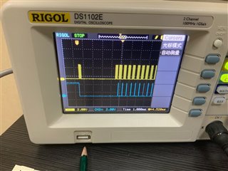
  • The above is the waveform of data pin and chip selection pin.(The yellow waveform is the data pin waveform. The blue waveform is the chip selection pin waveform. And chip selection is pin low level effective)

    Through the analysis of chip selection waveform and data, it is found that chip selection pin is always valid after the data transmission of the first byte, and invalid only after the data transmission of the second byte.Therefore, the data of the second byte is lost due to this problem.

  • The normal chip selection cycle is 500us. However, the first chip selection cycle is 4.34ms. 

  • The above engineering path is corrected to sdk15.3 examples\peripheral\spis\pca10040      (52832)

Related