This post is older than 2 years and might not be relevant anymore
More Info: Consider searching for newer posts

Is it possible to verify DCDC is working via Software testing

Dear Support Engineers

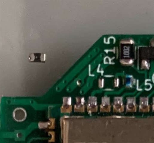
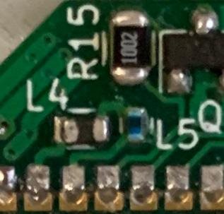
I am in the process of designing the automated testing platform for a 52832 based device and would like to test to make sure the components/devices are reflowed properly. Especially, I am concern that if L2 and L3 connected to DCC and DEC4 is not soldered on properly, we would not know as the board would just default to LDO operation. I would like to find out if it is possible to detect that the DC/DC is working properly without additional testing hardware. If this is not possible, how would you recommend the test be conducted automatically? I can think of 2 options:-

1) Having a external probe looking at DCC for buck operation waveforms as specified in the link below.
devzone.nordicsemi.com/.../212990

2) Measuring the current difference when transmitting with DC/DC enable and disabled.

It would seem to me that option 1 would be more complex. I am thinking of using option 2. Can you please let me know if it is possible to detect DCDC operation in software or if there is a simpler option 3 that I missed.

Best regards,

Nelson


  • Hi,


    If there is an inproper reflow between any of the DCDC inductors, the device will not work. This is a quite simple thing to test, but obviously there can be probably be other causes for this. You could then measure the output of DCC or the voltage level on DEC4 to verify if the cause is that the inductors are not soldered properly.


    Best regards,

    Andreas

  • Hi,

    I would have guess that if there is an improper reflow, the inductors would form an open circuit and therefore the device, failing to see the inductors, would still work but defaults to LDO mode. 

    I understand from you that if I have a working device that can transmit and receive, I can then measure the voltage at DCC and DEC4; and if both of them has a DC voltage of about 1.25VDC present, then we can assume that the DCDC is working properly, correct?

    Best regards,

    Nelson

  • Hi,


    Correct. Also during TX or RX you can of course measure the current consumption if you want.


    Best regards,

    Andreas

  • Thank you Andreas,

    Just to make sure I understand the behaviour, I have removed one of the 2 serial inductors in our custom board to simulate the case of improper reflow.

    As expected, the board would still works, possibly in LDO mode, but the DC voltage at DCC drop to about 10mV.

    Once the inductor has been reinstalled,

    voltage at DCC is restored back to normal level of about 1250mV.

    The voltage at DEC4 remains at about 1250mV(DC) with the inductor on or off. It seems like I only need to test the voltage at DCC pin and this should provide a quick way for testing whether the DCDC is working or not. Would you be able to duplicate my experiment and confirm my results?

    Thank you very much for your valuable input.

    Best regards,

    Nelson

  • Hi,


    What is the nRF52 doing when you measure this, is is sleeping or something? When you enable the DCDC converter, the DCDC converter is not necessarily on 100% of the time. There is a power management system that measures the load, and enables the DCDC converter when the load is large enough that the DCDC converter improves efficiency. This is typically when the CPU is active or the Radio is active.


    Best regards,

    Andreas

Related