This post is older than 2 years and might not be relevant anymore
More Info: Consider searching for newer posts

Arduino, Adafruit and Particle.io all use the nRF52840 SOC but none of them can be programmed through USB and the NRF Connect for Desktop

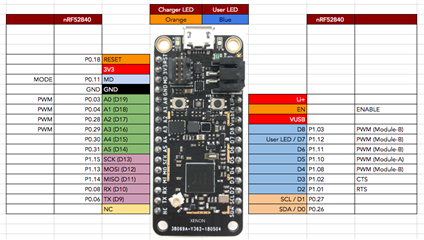
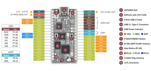
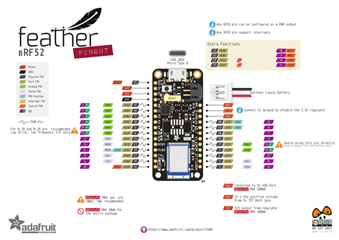
I have 3 Nordic nrf52840 USB dongles, several Particle Mesh Argons and have ordered an Arduino Nano 33 BLE Sense and have found the Adafruit Feather nRF52840 Express. All of these boards use the Nordic nRF 52840 SOC but the last three cannot be programmed using the "NRF Connect for Desktop".

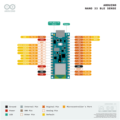
I would like to be able to program these boards with one consistent method and the NRF Connect For Desktop would be the best approach. I get that it is not Nordic's responsibility to spend time to connect these products, but perhaps they could direct me to some possible solutions. Each of these boards have different strengths: The Nordic board is inexpensive, the Nano 33 BLE Sense has many sensors on board, the Particle Argon has built in Wifi, the Adafruit board allows CircuitPython. 

If anyone can connect these boards, it would be the technicians at Nordic. Does anyone have any suggestions? I can generate a .hex file but how do I get it onto the boards. Is there any bootloaders that might work on all three? Can that bootloader be loaded using only the USB connection? I do not want to use a JTAG connection.

The advantage to Nordic is that a large BLE network could have many Nordic boards, but could also have some of these specialty boards when needed. Being able to switch between the different platforms would also be very useful.

  • Those are good resources. As I learn more, I understand better what to ask. 

    I guess I want to make sure I understand how to customize the nordic nrf52 sdk --> components --> boards folder, header files. For example the 10059.h 

    #ifndef PCA10059_H
    #define PCA10059_H
    
    #ifdef __cplusplus
    extern "C" {
    #endif
    
    #include "nrf_gpio.h"
    
    // LED definitions for PCA10059
    // Each LED color is considered a separate LED
    #define LEDS_NUMBER    4
    
    #define LED1_G         NRF_GPIO_PIN_MAP(0,6)
    #define LED2_R         NRF_GPIO_PIN_MAP(0,8)
    #define LED2_G         NRF_GPIO_PIN_MAP(1,9)
    #define LED2_B         NRF_GPIO_PIN_MAP(0,12)
    
    #define LED_1          LED1_G
    #define LED_2          LED2_R
    #define LED_3          LED2_G
    #define LED_4          LED2_B
    
    #define LEDS_ACTIVE_STATE 0
    
    #define LEDS_LIST { LED_1, LED_2, LED_3, LED_4 }
    
    #define LEDS_INV_MASK  LEDS_MASK
    
    #define BSP_LED_0      LED_1
    #define BSP_LED_1      LED_2
    #define BSP_LED_2      LED_3
    #define BSP_LED_3      LED_4
    
    // There is only one button for the application
    // as the second button is used for a RESET.
    #define BUTTONS_NUMBER 1
    
    #define BUTTON_1       NRF_GPIO_PIN_MAP(1,6)
    #define BUTTON_PULL    NRF_GPIO_PIN_PULLUP
    
    #define BUTTONS_ACTIVE_STATE 0
    
    #define BUTTONS_LIST { BUTTON_1 }
    
    #define BSP_BUTTON_0   BUTTON_1
    
    #define BSP_SELF_PINRESET_PIN NRF_GPIO_PIN_MAP(0,19)
    
    #define HWFC           true
    
    #ifdef __cplusplus
    }
    #endif
    
    #endif // PCA10059_H
    

    Seems to make sense. However the 10040.h file seems to have arduino references. That is what I am interested in. How to make custom headers for various boards that have the nrf52840 SOC.

    #ifndef PCA10040_H
    #define PCA10040_H
    
    #ifdef __cplusplus
    extern "C" {
    #endif
    
    #include "nrf_gpio.h"
    
    // LEDs definitions for PCA10040
    #define LEDS_NUMBER    4
    
    #define LED_START      17
    #define LED_1          17
    #define LED_2          18
    #define LED_3          19
    #define LED_4          20
    #define LED_STOP       20
    
    #define LEDS_ACTIVE_STATE 0
    
    #define LEDS_INV_MASK  LEDS_MASK
    
    #define LEDS_LIST { LED_1, LED_2, LED_3, LED_4 }
    
    #define BSP_LED_0      LED_1
    #define BSP_LED_1      LED_2
    #define BSP_LED_2      LED_3
    #define BSP_LED_3      LED_4
    
    #define BUTTONS_NUMBER 4
    
    #define BUTTON_START   13
    #define BUTTON_1       13
    #define BUTTON_2       14
    #define BUTTON_3       15
    #define BUTTON_4       16
    #define BUTTON_STOP    16
    #define BUTTON_PULL    NRF_GPIO_PIN_PULLUP
    
    #define BUTTONS_ACTIVE_STATE 0
    
    #define BUTTONS_LIST { BUTTON_1, BUTTON_2, BUTTON_3, BUTTON_4 }
    
    #define BSP_BUTTON_0   BUTTON_1
    #define BSP_BUTTON_1   BUTTON_2
    #define BSP_BUTTON_2   BUTTON_3
    #define BSP_BUTTON_3   BUTTON_4
    
    #define RX_PIN_NUMBER  8
    #define TX_PIN_NUMBER  6
    #define CTS_PIN_NUMBER 7
    #define RTS_PIN_NUMBER 5
    #define HWFC           true
    
    #define SPIS_MISO_PIN   28  // SPI MISO signal.
    #define SPIS_CSN_PIN    12  // SPI CSN signal.
    #define SPIS_MOSI_PIN   25  // SPI MOSI signal.
    #define SPIS_SCK_PIN    29  // SPI SCK signal.
    
    #define SPIM0_SCK_PIN   29  // SPI clock GPIO pin number.
    #define SPIM0_MOSI_PIN  25  // SPI Master Out Slave In GPIO pin number.
    #define SPIM0_MISO_PIN  28  // SPI Master In Slave Out GPIO pin number.
    #define SPIM0_SS_PIN    12  // SPI Slave Select GPIO pin number.
    
    #define SPIM1_SCK_PIN   2   // SPI clock GPIO pin number.
    #define SPIM1_MOSI_PIN  3   // SPI Master Out Slave In GPIO pin number.
    #define SPIM1_MISO_PIN  4   // SPI Master In Slave Out GPIO pin number.
    #define SPIM1_SS_PIN    5   // SPI Slave Select GPIO pin number.
    
    #define SPIM2_SCK_PIN   12  // SPI clock GPIO pin number.
    #define SPIM2_MOSI_PIN  13  // SPI Master Out Slave In GPIO pin number.
    #define SPIM2_MISO_PIN  14  // SPI Master In Slave Out GPIO pin number.
    #define SPIM2_SS_PIN    15  // SPI Slave Select GPIO pin number.
    
    // serialization APPLICATION board - temp. setup for running serialized MEMU tests
    #define SER_APP_RX_PIN              23    // UART RX pin number.
    #define SER_APP_TX_PIN              24    // UART TX pin number.
    #define SER_APP_CTS_PIN             2     // UART Clear To Send pin number.
    #define SER_APP_RTS_PIN             25    // UART Request To Send pin number.
    
    #define SER_APP_SPIM0_SCK_PIN       27     // SPI clock GPIO pin number.
    #define SER_APP_SPIM0_MOSI_PIN      2      // SPI Master Out Slave In GPIO pin number
    #define SER_APP_SPIM0_MISO_PIN      26     // SPI Master In Slave Out GPIO pin number
    #define SER_APP_SPIM0_SS_PIN        23     // SPI Slave Select GPIO pin number
    #define SER_APP_SPIM0_RDY_PIN       25     // SPI READY GPIO pin number
    #define SER_APP_SPIM0_REQ_PIN       24     // SPI REQUEST GPIO pin number
    
    // serialization CONNECTIVITY board
    #define SER_CON_RX_PIN              24    // UART RX pin number.
    #define SER_CON_TX_PIN              23    // UART TX pin number.
    #define SER_CON_CTS_PIN             25    // UART Clear To Send pin number. Not used if HWFC is set to false.
    #define SER_CON_RTS_PIN             2     // UART Request To Send pin number. Not used if HWFC is set to false.
    
    
    #define SER_CON_SPIS_SCK_PIN        27    // SPI SCK signal.
    #define SER_CON_SPIS_MOSI_PIN       2     // SPI MOSI signal.
    #define SER_CON_SPIS_MISO_PIN       26    // SPI MISO signal.
    #define SER_CON_SPIS_CSN_PIN        23    // SPI CSN signal.
    #define SER_CON_SPIS_RDY_PIN        25    // SPI READY GPIO pin number.
    #define SER_CON_SPIS_REQ_PIN        24    // SPI REQUEST GPIO pin number.
    
    #define SER_CONN_CHIP_RESET_PIN     11    // Pin used to reset connectivity chip
    
    
    // Arduino board mappings
    #define ARDUINO_SCL_PIN             27    // SCL signal pin
    #define ARDUINO_SDA_PIN             26    // SDA signal pin
    #define ARDUINO_AREF_PIN            2     // Aref pin
    #define ARDUINO_13_PIN              25    // Digital pin 13
    #define ARDUINO_12_PIN              24    // Digital pin 12
    #define ARDUINO_11_PIN              23    // Digital pin 11
    #define ARDUINO_10_PIN              22    // Digital pin 10
    #define ARDUINO_9_PIN               20    // Digital pin 9
    #define ARDUINO_8_PIN               19    // Digital pin 8
    
    #define ARDUINO_7_PIN               18    // Digital pin 7
    #define ARDUINO_6_PIN               17    // Digital pin 6
    #define ARDUINO_5_PIN               16    // Digital pin 5
    #define ARDUINO_4_PIN               15    // Digital pin 4
    #define ARDUINO_3_PIN               14    // Digital pin 3
    #define ARDUINO_2_PIN               13    // Digital pin 2
    #define ARDUINO_1_PIN               12    // Digital pin 1
    #define ARDUINO_0_PIN               11    // Digital pin 0
    
    #define ARDUINO_A0_PIN              3     // Analog channel 0
    #define ARDUINO_A1_PIN              4     // Analog channel 1
    #define ARDUINO_A2_PIN              28    // Analog channel 2
    #define ARDUINO_A3_PIN              29    // Analog channel 3
    #define ARDUINO_A4_PIN              30    // Analog channel 4
    #define ARDUINO_A5_PIN              31    // Analog channel 5
    
    
    #ifdef __cplusplus
    }
    #endif
    
    #endif // PCA10040_H
    

    Here are some pinout diagrams I have found

    .

    Finally I just found this library https://github.com/adafruit/Adafruit_DAP which allows an Arduino to reflash the bootloader for various architectures. It looks like Adafruit has recently added the Feather nRF52840  here

    It would be really interesting if Nordic could add the files necessary to flash their bootloader! This library could make it easy to flash a Nordic Bootloader onto the Arduino Nano 33 BLE, Adafruit Feather nrf52840, Particle Xenon so that all could be programmed using the Nordic nrf-connect for desktop software. 

    It would also make it possible to use an Arduino to reflash a corrupt nRF52840 USB Dongle bootloader without getting a special programmer such as a segger j-link.


  • The Arduino references in the board header files for the nRF52xxx DKs are there because the boards use the Arduino form factor. The defines have no effect unless they are used in the application code. You can create a similar board file for your other Arduino boards, but you can also define the pin numberings directly in the code. In the SDK examples, the main usage of the board header files is to defined LEDs, Buttons, and the TWI pins are also used from Arduino defines.

    The only official supported solution for programming Nordic devices is through the use of J-Link debuggers. You can also flash applications from other debuggers (and event Raspberry Pis) using OpenOCD etc, but these solutions are used at your own risk and are not something we provide support for.

    The nRF52840 Dongle is primarily intended for use with our development tools (nRF Connect application, etc). This is why there are no SWD pins soldered by default. It should not be possible to "corrupt" the bootloader of the dongle without connecting an external debugger to the device. Nordic does not share the private key required to generate update packages for the bootloader, preventing any customer or 3rd party to update the bootloader with an unofficial bootloader package.

  • Thanks again Jorgen. It looks like I will try the:

    Segger J-Link EDU mini which comes with a 10 pin cable

      $30 USD x 1  Segger J-Link EDU mini - JTAG/SWD Debugger https://www.amazon.com/Segger-J-Link-EDU-mini-Debugger/dp/B0758XRMTF/ref=sr_1_fkmr0_2?keywords=segger+edu+ssd&qid=1575614602&sr=8-2-fkmr0

    .
    I also think I should get the 10 pin tag-connector
    $ 39 USD  x    1 ‎TC2050-IDC-NL-ND‎   tag-connect cable   https://www.digikey.com/products/en?keywords=%E2%80%8ETC2050-IDC-NL-ND%E2%80%8E
    There are many programmer pins on the back of the nRF52840 USB dongle. Can you think of any other cable connectors that might easily fit?
    I feel like the pins below should be able to be used for programming but have never seen a connector that works with them. Any suggestions? Not sure if I can solderr wires to something that small.
  • I have used a header soldered to P1 and also soldered pins to SWDCLK/SWDIO that you have circled in the image to program the dongle. I'm not aware of any connectors that will fit with these pins. SB3-SB4 are solder bridges for disconnecting D+ and D- data lines to the USB connector, they are not used for programming.

    The Tag-connect cable should work with the Dongle, and you will also find these pads on most of our development kits.

  • Hello rocksetta,

    You can also try particles debugger which will cost you $12 to do the same trick. I just wrote an article after realising there was not any actual guide to show how to do it. see if it can help you solve your issue. https://genxnext.com/debug-particle-argon-with-segger-embedded-studio/

Related